circuit of HS60.pdf - 第97页
3 - 2 0033589 1-010 201LD3 Servo u nit with out bo ards (Sh . 1 of 2) X4vp/4 0 Volts Plain w asher Plain w asher Plain w asher Plain w asher X9ym Ballast Plain w asher Retain er ring Screw, M 5X12 X7v f/2 M6 nut +30 Volt…
3 - 1
3 Circuit Diagrams
00334809-010401LD3 HS60 control unit without cards
A
3
B
A
E
B
18
19
20
21
22
23
24
25
26
27
28
29
30
31
32
ba
XX
XX
X
X
X
X
X
X
X
X
X
X
X
X
X
X
a8
a10
a11
a14
+5V
GND
GND
-12V
1
2
3
4
5
6
7
8
9
10
11
12
13
14
15
16
17
19
20
21
22
23
24
25
26
27
28
29
30
31
32
ba
XX
XX
XX
XX
XX
X
XX
XX
X
12
34
X1ub
1
2
3
4
5
6
7
8
9
10
11
12
13
14
15
16
17
18
21.01.98
1
#
Dr. Fux
21.01.1998
08.08.01
08.08.01
01.
04.
01.
TB
TB
Tek
1
00334809-010401LD3
+ Pol
- Pol UBAT-
X1ub/1
X20/4
UBAT+
SD EA 1 R&D
P12X1ub/2
N12
Split ring
M5 nut
M5 nut
Contact washer
M5X12 screw
Washer
Ground wire
gnye (UL) / 1.5mm²
Side panel
wh (UL) / 0.34mm²
rd (UL) / 0.34mm²
Battery
Fan
bk (UL) / 0.34mm²
rd (UL) / 0.34mm²
Pin assignment
Fan connector
cable inlet side
Viewed from
FAN
Connecting video multiplexer:
EMV backplane
Video multiplexer X36 Video multiplexer X35
EMC Backplane
Locking clip, 14-pole
Flat screen 2
Flat screen 1
SIPLACE HS60 SMD Placement System
Sheet
Sh.
HS60 control unit
without cards
Repl. byRepl.f.Orig.Status
Function status
Product status
Docum. status
Modified Date Name Stand.
Check.
Author
Date
=
+
SIEMENS
DEMATIC
56
F
Video PC
R
G
B
H-Sync
V-Sync
R
G
B
H-Sync
V-Sync
R
G
B
H-Sync
V-Sync
1
45678
1234
F
C
D
D
C
E
2
87
3 - 2
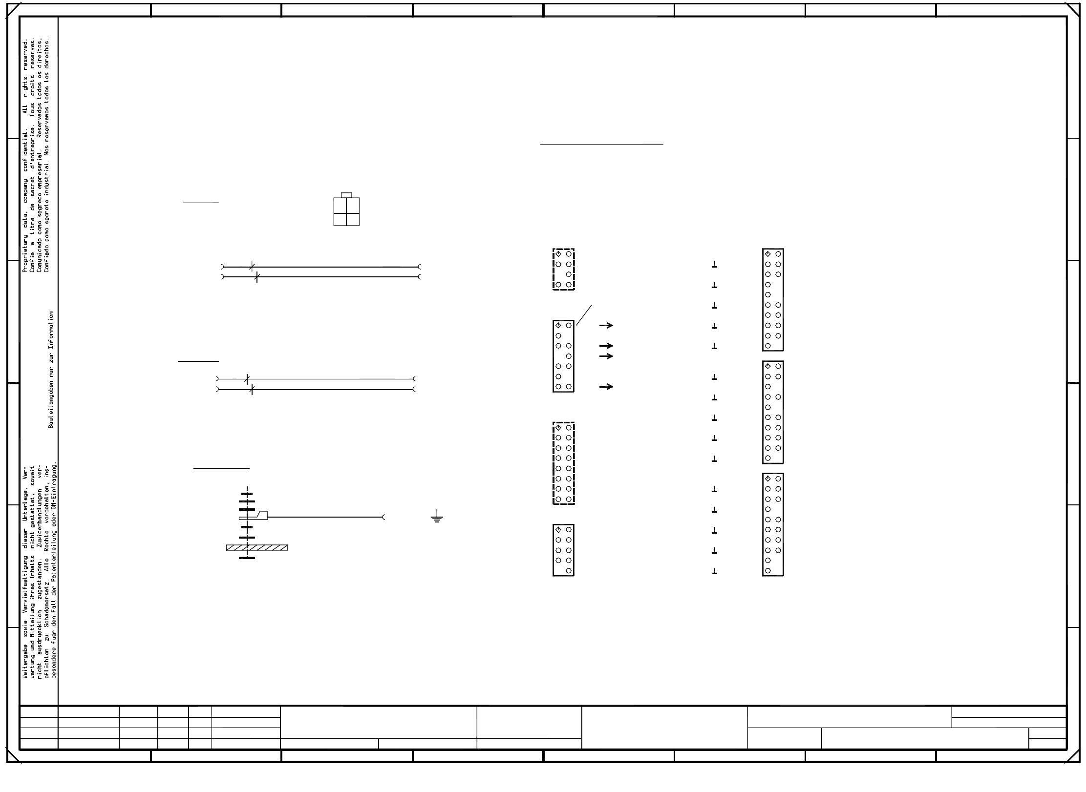
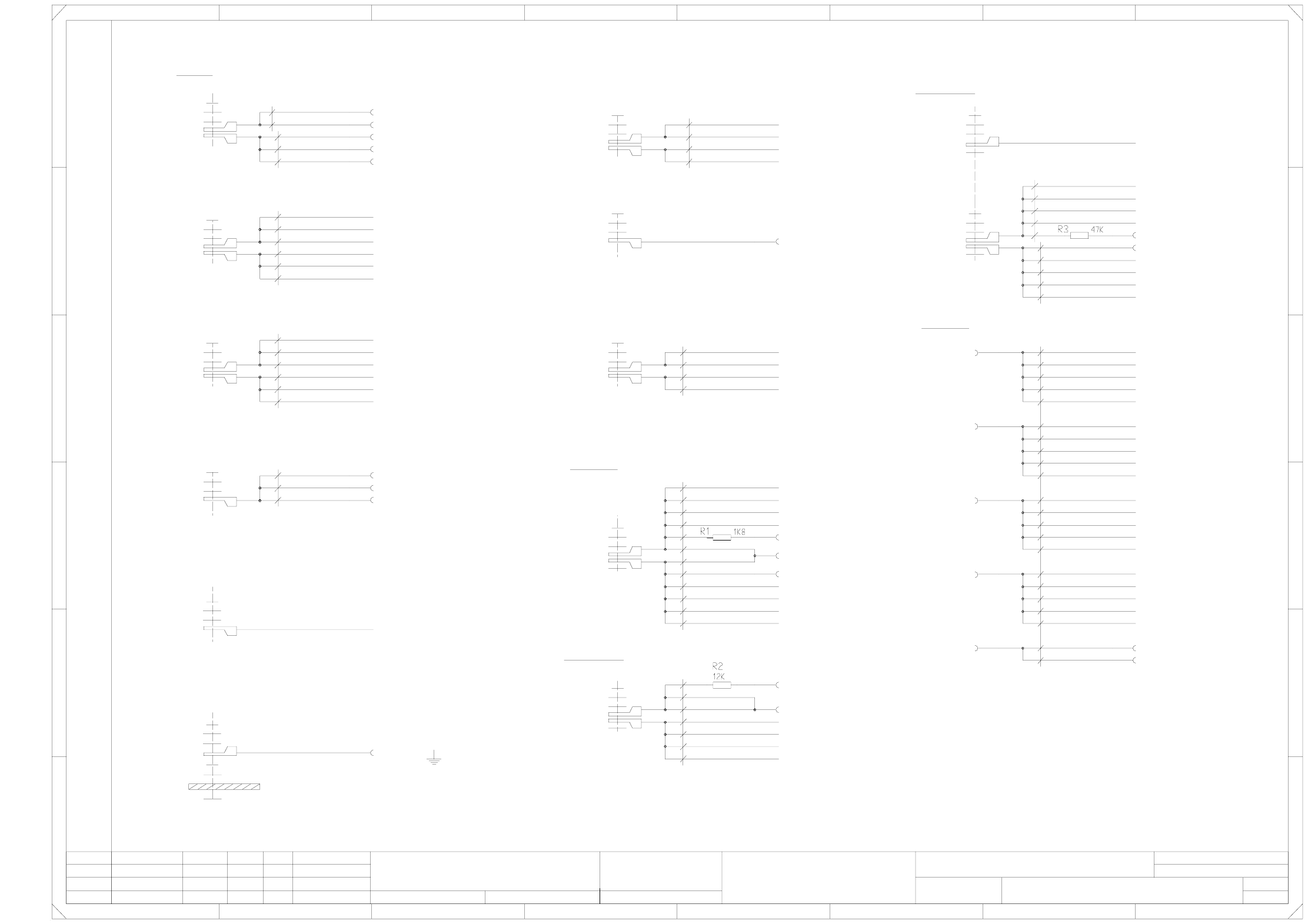
00335891-010201LD3 Servo unit without boards (Sh. 1 of 2)
X4vp/4
0 Volts
Plain washer
Plain washer
Plain washer
Plain washer
X9ym
Ballast
Plain washer
Retainer ring
Screw, M5X12
X7vf/2
M6 nut
+30 Volts
X1ym
Plain washer
Retainer ring
Screw, M5X12
wh (UL) / 1.0mm²
wh (UL) / 2.5mm²
X4vr/2
DP
2 45678
12345678
A
Screw, M5X12
X4vs/4
X4vw/4
X4vv/4
X4vo/4
X4vn/4
X4vr/4
X4vq/4
X4vu/4
X4vt/4
X4vm/4
M5 nut
B
C
D
E
X7vh/2
X7vd/2
X7vg/2
Screw, M5X12
X7vc/2
X10ym
X-P3
Y-P2
Y-P3
Plain washer
Retainer ring
wh (UL) / 2.5mm²
X-P2
wh (UL) / 2.5mm²
Plain washer
Retainer ring
Mutter M8
X6ym
N30
Plain washer
Retainer ring
Screw, M5X12
HEP
1
M6 nut
S-P2
X4vw/3
X4vu/3
DP-P3
DP-P2
Z-P3
Plain washer
X7vb/2
X7ve/2
Screw, M5X12
X7va/2
X8ym
X-P4
Y-P1
Y-P4
Plain washer
Retainer ring
wh (UL) / 2.5mm²
X-P1
X4vo/3
X60/1
X4vk/3
X3yn
gr (UL) / 0.75mm²
Retainer ring
M5 nut
wh / 0.34mm²
Anti-crash P1/P4
Retainer ring
Screw, M5X12
X4vk/4 S-P1
X4ym
Resistors R1-R3 (and their soldered joints) are insulated using heat-shrinkable sleeves !
DP-P1
Z-P4
Plain washer
Retainer ring
wh (UL) / 1.0mm²
Z-P1
X3ym
Power supply unit
TP 0V
Anti-crash P2/P3
wh (UL) / 1.5mm²
Power supply unit
Plain washer
From external power supply
X7ym
N200
X53/16
X7va/1
X-P3
Ballast
X-P2
X4vv/3
X52/32
DP-P1
Power supply unit
X2yn
X60/2
X4vq/3
X4vp/3
X4vt/3
3
Z-P4
P30
Z-P3
TP 30V
X-P1
Plain washer
Retainer ring
M6 nut
S-P4
S-P3
S-P2
DP-P4
DP-P3
DP-P2
X4vm/3
X4vn/3
X4vk/2
X6ve/2
X6va/2 X-P1
or / 0.34mm²
TP 6/100V
X2ym
S-P1
P6/100
Plain washer
Retainer ring
Z-P2
Y-P4
Y-P3
Z-P2
From external power supply
+15 Volts
+200 Volts
S-P4
DP-P4
X7vf/1
X7vh/1
X7vg/1
X7ve/1
X7vb/1
X7vd/1
X7vc/1
X-P4
bk (UL) / 1.5mm²
X4yn TP 200V
bk (UL) / 0.75mm²
X11ym
Plain washer
Retainer ring
M6 nut
X4vs/3
X6vc/2 X-P2
X5ym
S-P3
X60/4
1
Servo unit, without boards
#
Goller
21.01.1998
09.12.98
09.12.98
21.01.98
1.
2.
1.
Tek
Tek
Tek
2
00335891-010201LD3
X1yn
X53/22
X60/3
X52/16
X51/b31
X60/12
PL EA1 E2
X50/b31
X52/30
X60/11
=
SIEMENS AG
+
X-P3
+6/100 Volts
Anti-crash P2/P3
X52/12
Y-P2
Y-P1
X51/b30
X50/b30 Anti-crash P1/P4
X52/10
X4vw/2
X4vs/2
DP
Z
S
Y
X4vo/2
X6vh/2
X6vd/2
bk (UL) / 2.5mm²
Contact washer
Z
S
Y
X4vn/2
X6vg/2
Y
Lateral part
X4vr/3
Z-P1
X4vq/2
DP
Z
S
Y
X4vm/2
X6vf/2
X6vb/2 X-P4
X52/4
X4vt/2
X4vp/2
DP
Z
S
gnye (UL) / 2.5mm²
Plain washer
Retainer ring
M5 nut
X52/6
X4vu/2
X4vv/2
X52/8
FF
E
D
C
B
A
Weitergabe sowie Vervielfaeltigung dieser Unterlage, Ver-
wertung und Mitteilung ihres Inhalts nicht gestattet, soweit
nicht ausdruecklich zugestanden. Alle Rechte vorbehalten, ins-
besondere fuer den Fall der Patenterteilung oder GM-Eintragung. Bauteilangaben nur zur Information
Comunicado como segredo empresarial. Reservados todos os direitos.
Confie a titre de secret d'entreprise. Tous droits reserves.
Proprietary data , company confidential . All rights reserved.
Confiado como secrete industrial. Nos reservamos todos los derechos.
SMD-Placement System Siplace HS60
Product status
Doc. status
Function status
Status DateModified Name Stand. Orig. Replacement for Replaced by
Author
Date
Check.
Sheet
Sh.
3 - 3
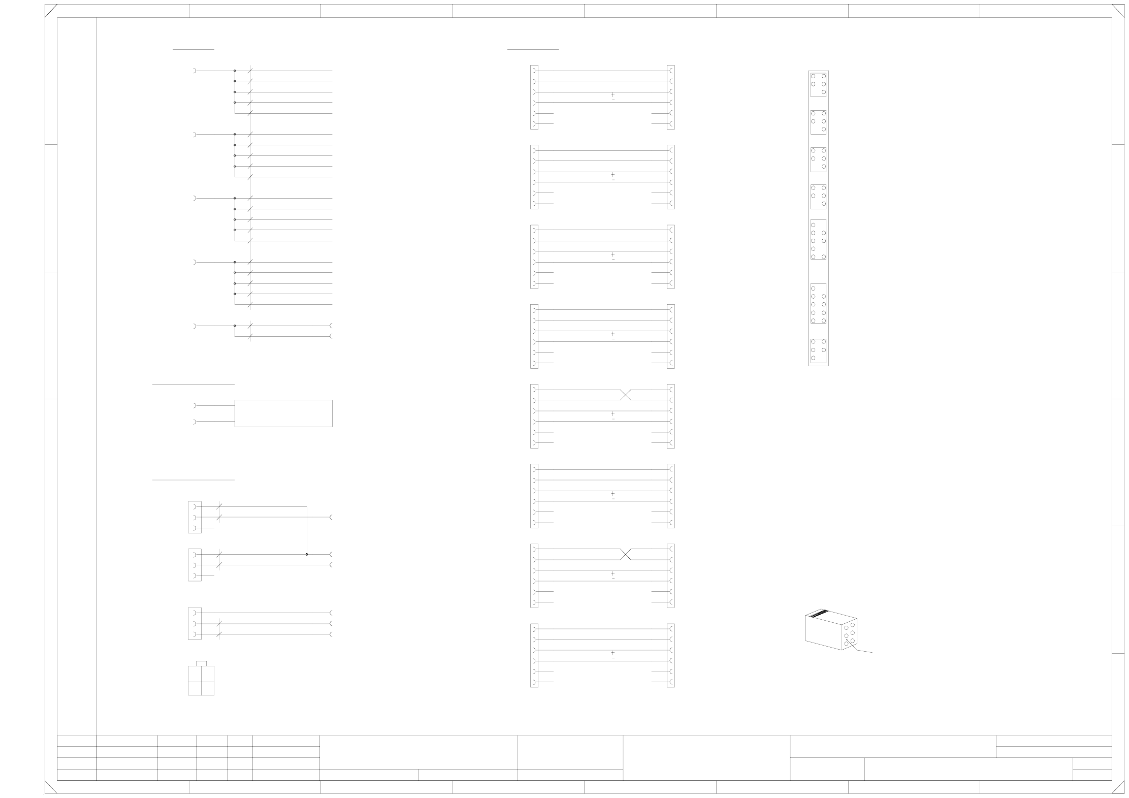
00335891-010201LD3 Servo unit without boards (Sh. 2 of 2)
=
SIEMENS AG
+
3
5
2
4
6
1
Enable
a21 = 0 Volts analog
Key Key
a28 = 0 Volts analog
8
123
Tacho-Y1
Enable
A
B
C
Weitergabe sowie Vervielfaeltigung dieser Unterlage, Ver-
wertung und Mitteilung ihres Inhalts nicht gestattet, soweit
nicht ausdruecklich zugestanden. Alle Rechte vorbehalten, ins-
besondere fuer den Fall der Patenterteilung oder GM-Eintragung. Bauteilangaben nur zur Information
Comunicado como segredo empresarial. Reservados todos os direitos.
Confie a titre de secret d'entreprise. Tous droits reserves.
Proprietary data , company confidential . All rights reserved.
Confiado como secrete industrial. Nos reservamos todos los derechos.
SMD-Placement System Siplace HS60
Product status
Doc. status
Function status
Status DateModified Name Stand. Orig. Replacement for Replaced by
Author
Date
Check.
Sheet
Sh.
Tacho-X4
Enable
Tacho-Y4
Enable
Tacho-X2
Enable
Tacho-Y2
Enable
Tacho-X3
Enable
Tacho-Y3
S
Z
DP
X4vp/1
Key Key
b28 = Distance sensor, analog
Ventilation OK
X60/9
P24
a26 = Distance sensor, digital
Key Key
Key
Key Key
Key
Key Key
b21 = Distance sensor analog
b27 = B2-prox. switch Y4 [Y3]
a19 = Distance sensor, digital
132 4567
Y
S
Z
DP
4 78
5
9
13
D
E
FF
Key
Key
Enable
Key
Key
Y
S
Z
DP
X4vs/1
X4vw/1
X52/24
bl / 0.34mm²
X-P1
X6va/1
X6ve/1
X4vk/1
Y
Y1 [Y2] - gantry
X4 [X3] - gantry
Y4 [Y3] - gantry
b
X51b7
X51a13
X51b13
b31 = 0 Volts
a31 = Crash signal
b32 = -15V
17
24
b17 = Ref. prox. switch X1 [X2]
b18 = B2-prox. switch X1 [X2]
Null
Key
Key
0.34mm²
X6vb/1
X6vf/1
X4vm/1
Y
S
Z
DP
X4vq/1
X4vu/1
X52/20
X-P2X6vc/1
X6vg/1
X4vn/1
X1ua/2
X1ua/1
X
X
X4vr/1
X4vv/1
X5va/3
C
B
A
X50a10
X50a9
X50b9
XX
X
XX
X
X50 [X51]
X1 [X2] - gantry
Gantry 1 [2]
Gantry 4 [3]
(Prox. switches)
(Prox. switches)
X=pinched off
1
30
X5vb/6
X5vc/2
X5vc/1
X5vc/4
a
a30 = Control On
b30 = +15V
X
X
X
65
b20 = B2-prox. switch Y1 [Y2]
b24 = Ref. prox. switch X4 [X3]
b25 = B2-prox. switch X4 [X3]
b26 = Ref. prox. switch Y4 [Y3]
X5vg/3
X5vg/6
X5vh/2
X5vh/1
X5vh/4
X5vh/3
X5vh/6
pk
vi
X60/6 Control On
bn
X1ua
bn
Crash signal P2/P3
X50a3
X50b3
X5va/2
X5va/1
X
E
D
X51a15
X51b15
X5vf/2
X5vf/6
X5vg/2
X5vg/1
X5vg/4
X51b1
X51a2
X51b2
X51a3
X51b3
X51a9
X51b9
X51a10
X51b10
X51a11
X51b11
X5vb/2
X5vb/1
X5vb/4
X5vb/3
X50/a32
X51/a30
X51/a31
X51/a32
X5vc/3
X
X
X5vd/1
X5vd/4
X5vd/3
X
X
X
X50a6
X50b6
X50a7
X50b7
0.34mm²
gn / 0.34mm²
0.5mm²
rd (UL)
bk (UL)
12
34
Viewed from
cable entry side
X50a1
X50b1
X50a2
X50b2
X50a5
X50b5
X52/22
X-P3
X5va/4
X51a14
X51b14
X6vd/1
X6vh/1
X4vo/1
X5vf/1
X5vf/4
X5vf/3
X50b10
X50a11
X50b11
X51a1
bl / 0.34mm²
Anticrash P1/P4X50/b32
X51/b32
X52/26
Anticrash P2/P3
-15 Volts
Ballast resistor
External
Ballast resistor
X53/10
X53/30
Anti-crash/fan
X50/a30
X50/a31
Tacho-X1
Anticrash
X60/8
X60/7
X60/5 Crash signal P1/P4
X60/10
X
X51a7
XX
X5ve/2
X5ve/1
X5ve/4
X5ve/3
X5ve/6
b19 = Ref. prox. switch Y1 [Y2]
X50a13
X50b13
X50a14
X50b14
X50a15
X50b15
X51a5
X51b5
X51a6
X51b6
X
X1ua/4
X5vc/6
X5vd/2
X5vd/6
2
Tek
Tek
Tek
1.
2.
1.
21.01.98
09.12.98
09.12.98
21.01.1998
Goller
#
Servo unit without boards
2
X
X4vt/1
X52/18
X-P4
X5va/6
00335891-010201LD3
PL EA1 E2
the numerical sequence of a Locking-clip connector
Make sure that ...
must be as viewed from the rear side of the casing.
Cable