Instrucciones de uso_HF3_14_es.pdf - 第616页
21 2KE0041502 - englisch_BA 04.1 1.2010 ENGLISH 6.2 Refrigeration Circuit After the activities on the water circuit have been completed, the motor protecting switches of the compressors have to be placed to the -1- posit…
20
2KE0041502 - englisch_BA
04.11.2010
ENGLISH
Depending on the specific version, the process cooler is optionally equipped with a
control switch, a remote control unit or a stand-by button (control On / OFF).
See circuit diagram.
6.1.2 Commissioning of Single and Two-Circuit Systems
Activities to be performed:
Place power disconnect switch (main switch) to the „0“ position
Place all motor protecting switches, control switches and automatic circuit breakers to the „0“
position
Remove tank filler cap
Fill up tank with water up to the –MAX- mark on the filling level indicator
Vent pump(s) via the vent screw on the pump housing
Place circuit breakers and motor protecting switches for pump(s) and fan(s) to the „1“ position
(see circuit diagram)
Activation of the pump(s) via disconnect switch, control switch in „1“ position
Check pump(s) for proper direction of rotation (see arrow on drive motor)
In the event that the pump rotates in the wrong direction, disconnect the process
cooler from the mains power supply and reverse any 2 phases of the main power
cable.
Visually inspect entire water circuit for leaks
Check that the water level is within the permissible range by inspecting the water level indicator
and top up, if necessary
Mount tank filler cap
6. Commissioning
21
2KE0041502 - englisch_BA
04.11.2010
ENGLISH
6.2 Refrigeration Circuit
After the activities on the water circuit have been completed, the motor protecting switches of
the compressors have to be placed to the -1- position (see circuit diagram in the appendix).
Acknowledge all fault messages that may be signalled on the control panel.
The process cooler is not operational, the control and operating unit takes over the control of
the water outlet temperature.
Check set-point settings and change, if necessary.
7. DECOMMISSIONING
The safety notices contained in Chapter 1 must be complied with !
Disconnect process cooler from power supply.
Completely drain water circuit, including tank, pump(s), pipes and filters
(see flow diagram of pipes and instruments in the appendix)
Take freeze protection measures (consult manufacturer)
8. SHUTDOWN IN EMERGENCIES
The safety notices contained in Chapter 1 must be complied with !
Turn power disconnect switch (main switch) on the process cooler to „off“
9. ENVIRONMENTAL REQUIREMENTS
When repairing or placing the process cooler out of service (decommissioning), the
environment-relevant requirements regarding recovery, reuse and disposal of fuels/oils and
components according to DIN EN 378 are to be complied.
The operator of the process cooler is responsible for the proper disposal of used fuels,
oils and system components.
The disposal of the water containing additives is to be effected in agreement with the
competent local authorities.
7. Decommissioning
8. Shutdown in Emergencies
9. Envirnomental Requirements
22
2KE0041502 - englisch_BA
04.11.2010
ENGLISH
10. OPERATION OF CONTROL AND OPERATING UNIT
The process cooler is switched on by means of the power disconnect switch (main switch)
which also doubles as EMERGENCY STOP switch.
The process cooler is now operational, the control and operating unit takes over the control of
the water outlet temperature.
It is not possible to start up the unit if there is an active low water level or dry run protection
signal.
10. Operation of Controland Operating Unit
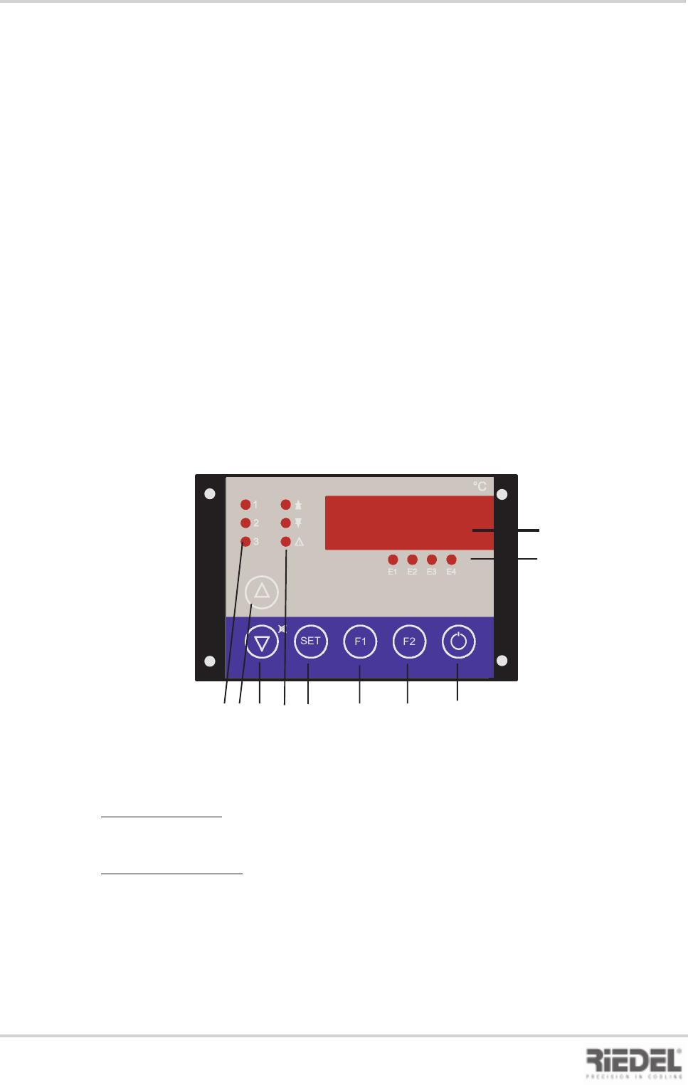
10.1 Control and Operating Unit ST 501
1 Display
2 Status displays
E1 Pump+water level status
E2 High pressure status
E3 Low pressure status
E4 TK fan status
3 Control modes
1 Pump on
2 Control setting 1 on
3 Control setting 2 on
4 UP button
to increase setpoint or parameter value
5 DOWN button
to decrease setpoint or parameter value
Actual values
Version with tank:
In the normal state, the flow temperature of the water circuit is indicated on the display.
Version without tank:
In the normal state, the return temperature of the water circuit is indicated on the display.
Press button F2 to display the flow temperature.
Setpoint adjustment
The setpoint is adjusted by simultaneously pressing the SET button and the UP or DOWN
button.
1
2
3
SET
E1
E2 E3
E4
F1
F2
°C
1
2
3 4 5 6 7 8 9 10
Control and Operating Unit ST 501
6 Alarm displays
Arrow Up“ fixed setpoint control, upper
limit value, f. differential control
„Arrow Down“ fixed setpoint control,
lower limit value, f. differential control
„Alarm“ common fault alarm
7. SET call-up of setpoint or parameter
display
8 F1 button -> special function after
parameter enabling
9 F2 button -> special function after
parameter enabling
10 Stand-by button controller On / Off
Option