Instrucciones de uso_HF3_14_es.pdf - 第621页
26 2KE0041502 - englisch_BA 04.1 1.2010 ENGLISH 1 3 . MALFUNCTIONS / TROUBLESHOOTING The safety notices contained in Chapter 1 must be complied with ! The basis for troubleshooting is the circuit diagram, the flow diagra…
25
2KE0041502 - englisch_BA
04.11.2010
ENGLISH
The visual inspection comprises:
Checking the air filter mats of the condenser for cleanliness
Checking the intactness of the joint sealing in the refrigeration circuit (pipe joints at
compressor) (red seals)
Visual inspection of the refrigeration circuit for oil leaks in the area of the compressor and
condenser connecting lines (suction line, pressure line)
Inspection of the condenser heat exchanger surface and the refrigerant piping for corrosion
damage
Inspection of the mounting and attachment of all piping and components for security
Visual leakage inspection of the water circuits under operating conditions
Check that operating manual is available on site.
The repeat tests must be documented in the system logbook.
12. Regular Performance Tests
26
2KE0041502 - englisch_BA
04.11.2010
ENGLISH
13. MALFUNCTIONS / TROUBLESHOOTING
The safety notices contained in Chapter 1 must be complied with !
The basis for troubleshooting is the circuit diagram, the flow diagram and the messages
displayed on the control panel.
The controlled variable is the main setpoint.
Displays on the Control Panel
See Chapter Operation of Control and Operating Unit
13.1 Malfunctions / Troubleshooting Control and Operating Unit ST 501
E1 to E4 illuminate
- when the process cooler is ready for operation.
Arrow UP or arrow DOWN illuminates
- In the differential control mode, setpoint limits for changeover to
fixed setpoint control are parameterised.
- When the limit values are exceeded or fallen short of, the corresponding LED
illuminates.
Fault displays:
F1 – F8 will flash in alternation with the display of the actual value.
13. Malfunctions / Troubleshooting
Fault Display Malfunction / Cause Remedy
No display
No voltage present
Main switch not turned on Place main switch in position -1-
Automatic control circuit breaker has tripped Check automatic control circuit breaker
Control voltage not enabled
Remote control not switched on Check remote control, check jumper wire
across terminals in control cabinet in
accordance with circuit diagram
F1
Sensor error Sensor 1
Sensor 1 break or short-circuit Check sensor, replace if necessary
F2
Sensor error Sensor 2
Sensor 2 break or short-circuit Check sensor, replace if necessary
27
2KE0041502 - englisch_BA
04.11.2010
ENGLISH
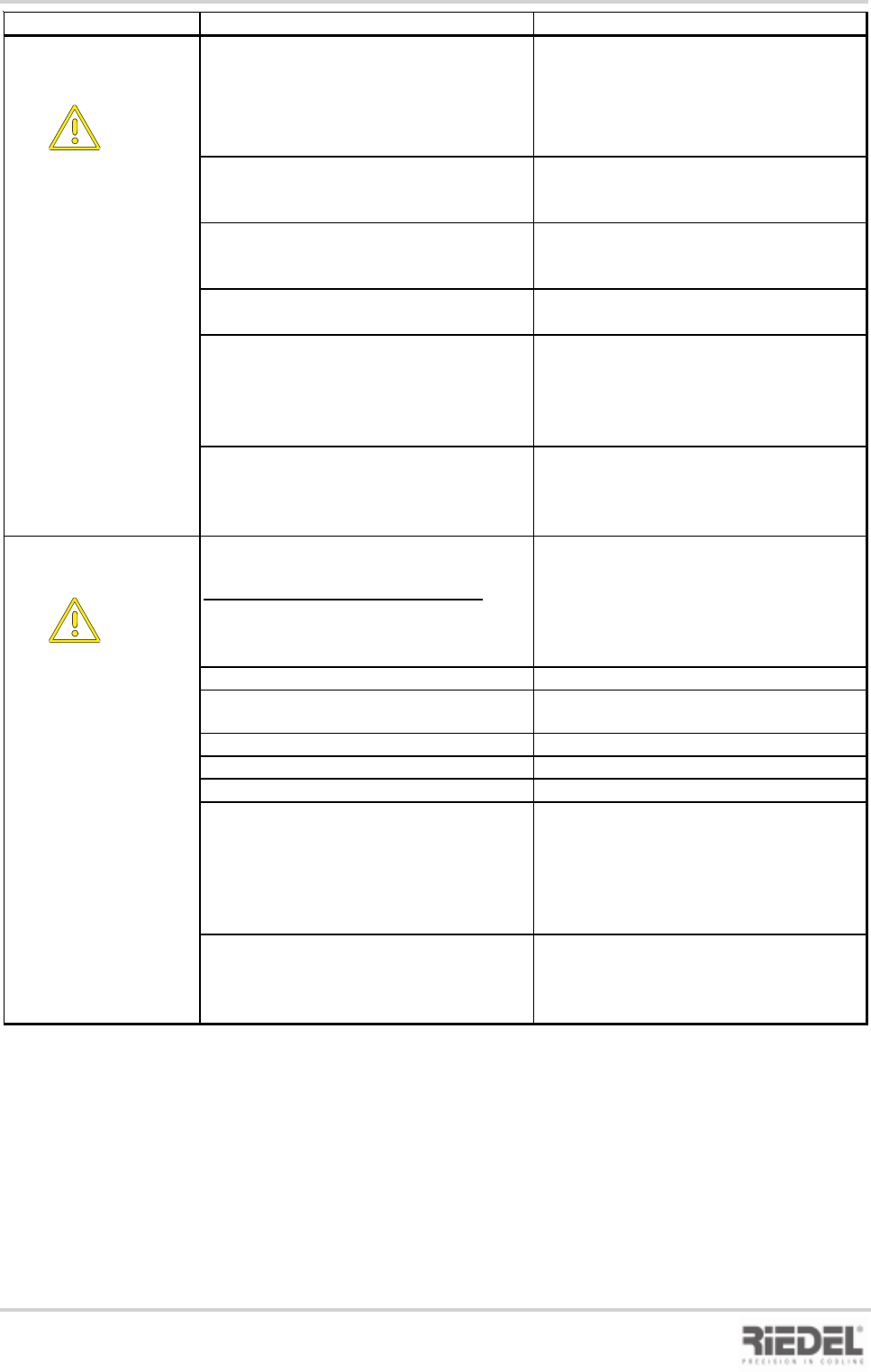
13. Malfunctions / Troubleshooting
Fault Display Malfunction / Cause Remedy
F3
E1 - off
Pump motor protecting switch has tripped
Pump motor overloading due to
mechanical sluggishness
Check pump, replace if necessary
Place motor protecting switch in position -1-
Float switch has tripped
Check float switch,
replace if necessary
Liquid loss in water circuit Check water circuit for leaks,
fill tank com pletely with water
Leaks at pump or pump seal
Replace pump, replace seal
Water is evaporating, (tank filler cap missing
)
Install tank filler cap
Water shortage results in:
- Shutdown of pump and compressor
Acknowledge/reset fault by means of
DOWN button
F4
E2 - off
High-pressure fault
High-pressure pressostat has tripped
Cooling air temperature too high
Ensure adequate heat dissipation through
increased air changes at the installation site
Fans fail to rotate Perform functional check of fans
Condenser or filter mat contaminated Clean condenser with compressed air
(do not damage fins) or replace filter mat
Water temperature too high
Drain water and top up with fresh water
Load too high
Reduce load or shut off load
Panel assemblies not mounted to unit Mount panel assemblies
Cooling operation is resumed after the
pressure has dropped to an acceptable
level and the RESET button on the
pressostat has been pressed
Acknowledge/reset fault by means of
DOWN button