00193897-0302_AI_MTC2+BE_DE+EN.pdf - 第104页
Assembly instructions MTC2 and Component docking unit on SIPLACE HF and X-se ries Edition 07/2009 102 Mount parts from retrofit kit : The following part s must be mounted or fitted: 1. Cover long EGS centre 2. Barcode fo…
Assembly instructions MTC2 and Component docking unit on SIPLACE HF and X-series
Edition 07/2009
101
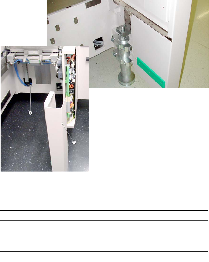
: Stow connectors, couplings and further cable material in the opening in the machine frame. (1).
: Fit the side covers (2) of
the machine frame.
2
Fig. 2.7.4 Component docking unit with outer cover (HF-series, location 2-4).
: If provided, mount the conveyor cover, nozzle changer and reject bin sensors. For further in-
formation, see the latest
instructions:
00193892-xx Assembly instructions conveyor cover SIPLACE HF-series / X-series / D3
00193756-xx Assembly instructions nozzle changer SIPLACE HF-series
00194550-xx Assembly instructions reject bin sensors SIPLACE HF-series
00194482-xx Assembly instructions nozzle changer SIPLACE X-series
00
194716-xx Assembly instructions reject bin sensors SIPLACE
X-series
2
2
Assembly instructions MTC2 and Component docking unit on SIPLACE HF and X-series
Edition 07/2009
102
Mount parts from retrofit kit
: The following parts must be mounted or fitted:
1. Cover long EGS centre
2. Barcode foil X sector 2 or barcode foil X sector 4
3. Machine cover X-F cover cpl./
Machine cover X-S cover cpl./
4. Protection X-HS R barcode panel cpl.
5. Wasteþtape chute
2
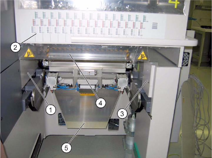
Fig. 2.7.5 SIPLACE HF location 2/4 (1-gantry placement area).
2
: Fit the cover over the pneumatic unit or power supply.
2
Assembly instructions MTC2 and Component docking unit on SIPLACE HF and X-series
Edition 07/2009
103
2.8 Installation of component docking unit for X-tape
feeders on a SIPLACE X-series
2
This component docking unit is not approved for HF and D3.
00378465-xx Retrofit kit component docking unit X
2
2
2
2
Prior to installation of the component docking unit, ensure that the tape cutter control PCB is
coded for the correct location (see jumper marking on control PCB). For further information, see
imprint on tape cutter control PCB. 2
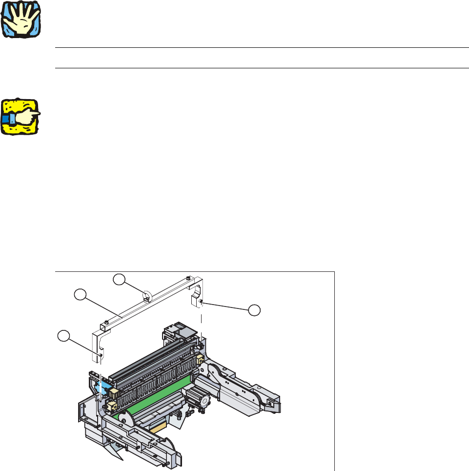
: Mount the fit-up aid (2) on
the fasteners (1) provided on the component docking unit.
: Attach the lifting device to the eye (3) of the fit-up
aid (2).
2
1. Fixing
2. Fit-up aid f. carriage or entering /X-S (03015976-)
3. Eye
1
1
3
2
2
2
2