00193897-0302_AI_MTC2+BE_DE+EN.pdf - 第107页
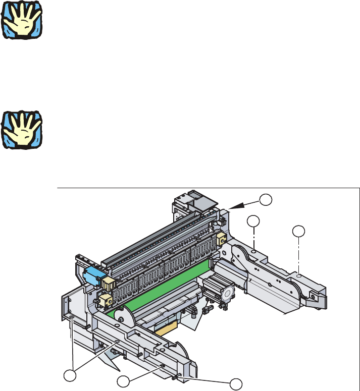
Assembly instructions MTC2 and Component docking unit on SIPLACE HF and X-series Edition 07/2009 105 , 2 Fig. 2.8.1 Position of docking unit frame
Assembly instructions MTC2 and Component docking unit on SIPLACE HF and X-series
Edition 07/2009
104
2
Heavy machine component:
The component docking unit is very heavy. For lifting purposes, the fit-up aid and suitable lifting
equipme
nt must be used (hand crane, etc.). 2
: Suitable gloves must be worn for lifting the
component docking unit in position.
Gloves reduce the risk of cuts caused by the bla
de of the tape cutter.
: Lift the component docking unit out of the machine with
the aid of the lifting device.
2
Ensure that the cables and hoses are not damaged. 2
2
: Remove the fit-up aid12.
1
1
3
1
1
2
2
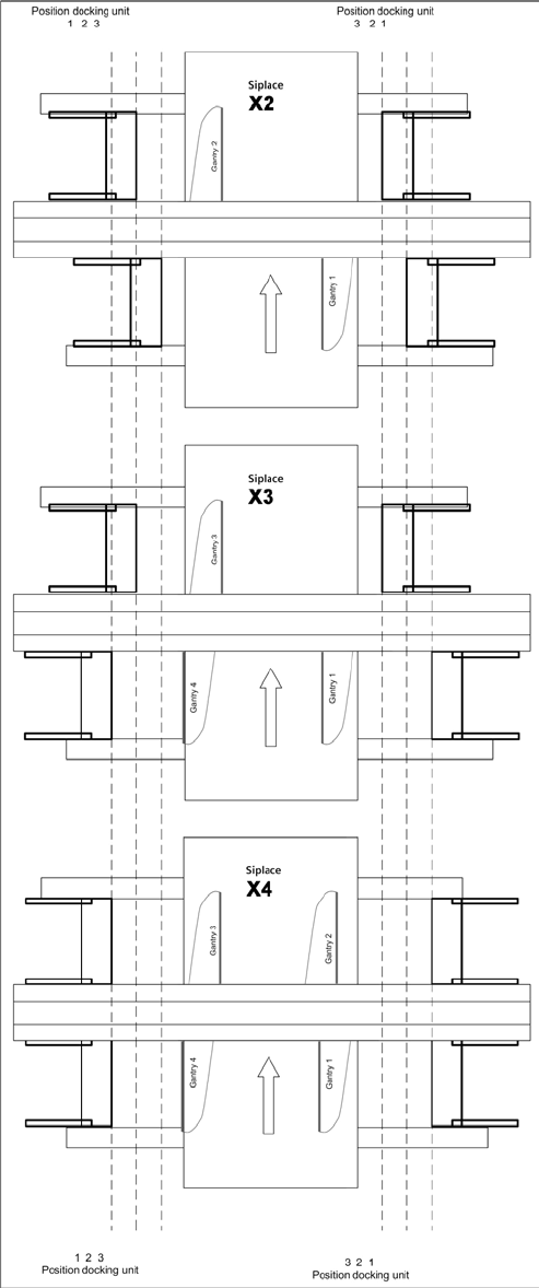
: Push the component docking unit into the correct position. See diagram ‘Assembly positions
according to machine type and location’.
2
Assembly instructions MTC2 and Component docking unit on SIPLACE HF and X-series
Edition 07/2009
105
, 2
Fig. 2.8.1 Position of docking unit frame

Assembly instructions MTC2 and Component docking unit on SIPLACE HF and X-series
Edition 07/2009
106
2
2
Observe sequence:
The reamed bolt must be tightened first and then th
e other fixing bolts. This ensures correct seat-
ing of the docking unit.
2
: Screw in the reamed bolt and then the fixing bolts without tightening.
: First tighten the reamed bolt, then the fixing
bolts on the inside of the machine.
2
: Re-establish all electrical connections.
: Connect compressed-air lines to the compressed-air connectors.