00193897-0302_AI_MTC2+BE_DE+EN.pdf - 第118页
Assembly instructions MTC2 and Component docking unit on SIPLACE HF and X-se ries Edition 07/2009 116 2 With the HF series, the MTC can only be used at locations 2 and 4 for a 1-ga ntry placement area. 2 2 2 Ensure that …
Assembly instructions MTC2 and Component docking unit on SIPLACE HF and X-series
Edition 07/2009
115
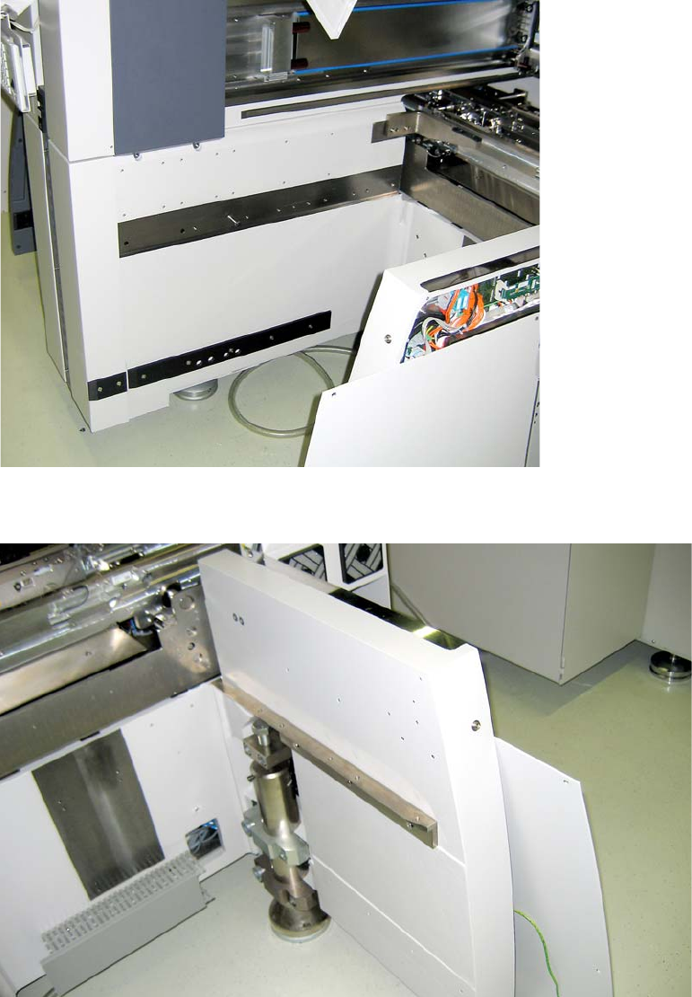
2.10.2 Installation of the MTC2 in SIPLACE HF (Series No. up to A001)
The machine should now be as follows:: 2
2
Fig. 2.10.1 HF series locations 2 and 4
2
Fig. 2.10.2 HF-series Location 2 bzw. 4
Assembly instructions MTC2 and Component docking unit on SIPLACE HF and X-series
Edition 07/2009
116
2
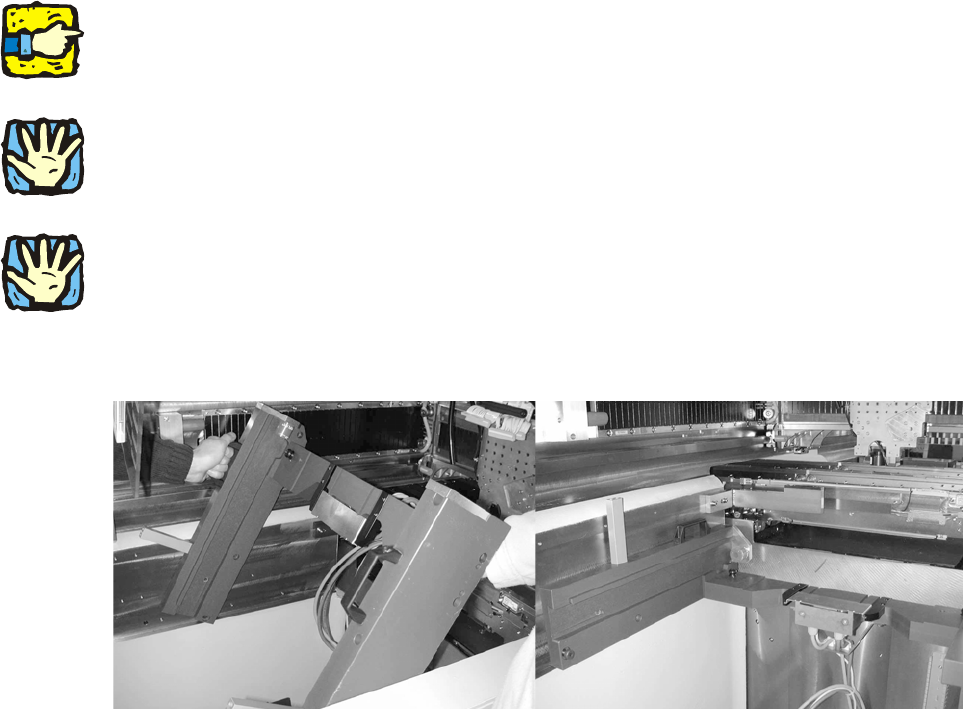
With the HF series, the MTC can only be used at locations 2 and 4 for a 1-gantry placement area.
2
2
2
Ensure that the cables and hoses are not damaged.
2
2
2
Heavy machine component! Two people should lift the slide-in framework into the machine.
2
: Install the MTC2 slide-in framework in the placement machine.
2
2
2
2
2
2
2
2
2
2
2
2
2
2
Assembly instructions MTC2 and Component docking unit on SIPLACE HF and X-series
Edition 07/2009
117
2
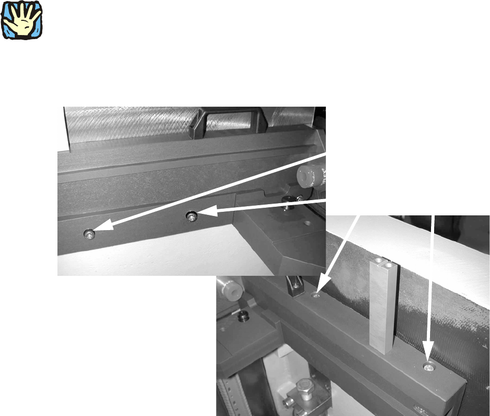
Observe sequence:
The reamed bolt must be tightened first and then the othe
r fixing bolts. This ensures correct sea-
ting of the MTC slide-in framework. 2
: Screw in the reamed bolt and then the fixin
g bolts without tightening.
: First tighten the reamed bolt, then the fixing bolts on the inside of the machine.
Reamed bolt
Regular bolts
2