00193897-0302_AI_MTC2+BE_DE+EN.pdf - 第120页
Assembly instructions MTC2 and Component docking unit on SIPLACE HF and X-se ries Edition 07/2009 118 : Fix the protective cover to the placement machine with two bolt s. 2 : The barcode p anels of the protective co ver …
Assembly instructions MTC2 and Component docking unit on SIPLACE HF and X-series
Edition 07/2009
117
2
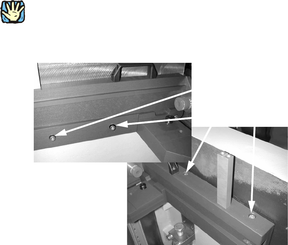
Observe sequence:
The reamed bolt must be tightened first and then the othe
r fixing bolts. This ensures correct sea-
ting of the MTC slide-in framework. 2
: Screw in the reamed bolt and then the fixin
g bolts without tightening.
: First tighten the reamed bolt, then the fixing bolts on the inside of the machine.
Reamed bolt
Regular bolts
2
Assembly instructions MTC2 and Component docking unit on SIPLACE HF and X-series
Edition 07/2009
118
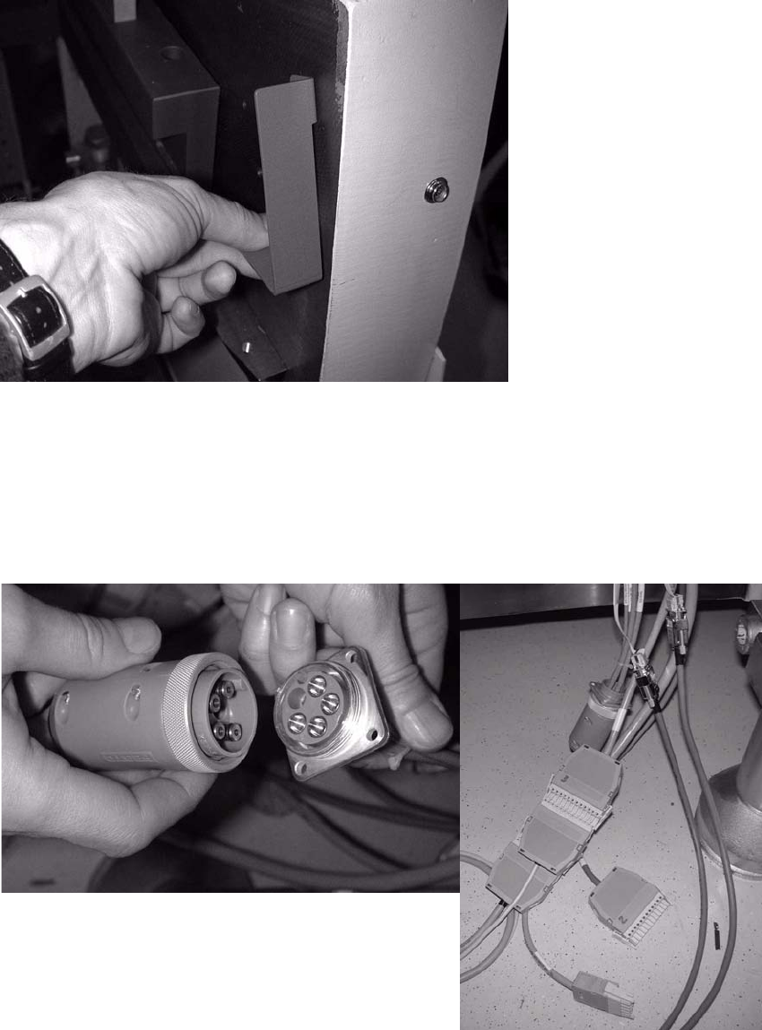
: Fix the protective cover to the placement machine with two bolts.
2
: The barcode panels of the protective cover are located above the conveying areas:
Change the barcode panels of the docking unit to
those for the MTC2.
: Insert the blind plugs in the compressed-air hose.
: Reconnect the cable.
2
2
3
B
A
4
5
BB
AA
B
A
B
A
B
A
B
A
Brücke
zu SIPLACE
B
A
XS_Sicherheitsschleife_Siplace2
XS_Sicherheitsschleife_Meldung_Ausgang
XS_Sicherheitsschleife_Meldung_Eingang
XS_Sicherheitsschleife_MTC2
XS_Sicherheitsschleife_MTC1
ws
/4.7
/4.7
/4.7
/4.7
/4.7
ws
sw
br
gr
rt
bl
XS_Sicherheitsschleife_Siplace1
/4.7
NYSYÖ-J 7x1.0mm²
-W035
Wago 12-polig, Stift
zu SIPLACE
3
4
5
6
7
8
9
A
B
6
4
3
B
A
B
A
5
B
A
B
A
8
7
B
A
B
A
B
A
9
B
A
10
A
B
2
A
B
A
B
6
-XS_ODU.3
B
Feld 3
1
8
BB
7
AA
BB
9
AA
B
A
B
A
B
2
A
B
Wago 12-polig, Stift
-X1*2
A
B
AA
BB
A
BBB
AA
A
B
A
B
2
br
Feld 1
-XS_ODU_1
CAN-Bus
-X1*6
B BA BA AA B B
D_SUB 9-polig, Buchse
CANH
=SIPLACE
-X1*6
GND CANL GND
=SIPLACE
-X1*5
D_SUB 9-polig, Stift
A
Stellplatzkodierung
Schirm
A
B
A
-XS_ODU_2
1
Feld 2
B
A
CAN_GND1_SIPLACE
CAN_H_SIPLACE
CAN_GND2_SIPLACE
CAN_L_SIPLACE
CAN_SHLD1_SIPLACE
-XS_ODU
/18.8
/18.8
/18.8
/18.8
/18.8
0,25 mm²
0,25 mm²
0,25 mm²
br
-W025
ge
ws
0,25 mm²
0,00 mm²
gn
Schirm
LiYY 4x0,34mm²
-W030
gn
ADR0_1
/18.8
ADR1_1
ADR_GND
/18.8
/18.8
Sicherheitsschleife
A
B
10
12
-X112
=SIPLACE
BBB
AAA
11
AA
BB
10
A
-X1*5
A
B
A
B
B
A
B
A
A
B
A
B
A
B
A
B
B
A
B
A
B
A
Assembly instructions MTC2 and Component docking unit on SIPLACE HF and X-series
Edition 07/2009
119
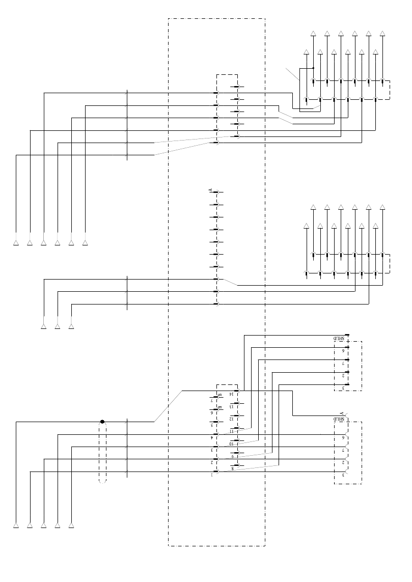
2
Fig. 2.10.3 Circuit diagram slide-in framework MTC2