00193897-0302_AI_MTC2+BE_DE+EN.pdf - 第125页
Assembly instructions MTC2 and Component docking unit on SIPLACE HF and X-series Edition 07/2009 123 2.1 1 Inst allation of the MTC2 in SIPLACE HF-series (Series No. from A001) and X-series 2 2 With the X-series, it is p…
Assembly instructions MTC2 and Component docking unit on SIPLACE HF and X-series
Edition 07/2009
122
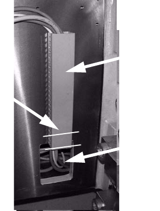
: Shorten the cover strip of the cable duct by 3 segments or teeth (see diagram below).
: Route the cable in the cable duct and push the long
cable back into the machine frame.
Shorten here
Cable duct
Pushed back cable
2
2
2
Assembly instructions MTC2 and Component docking unit on SIPLACE HF and X-series
Edition 07/2009
123
2.11 Installation of the MTC2 in SIPLACE HF-series
(Series No. from A001) and X-series
2
2
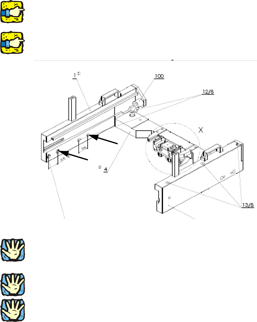
With the X-series, it is possible in the 2-gantry placement area to install the MTC at locations 2 or
4. The slide-in framework of the MTC (03009963-) must at least have the function status 03. Only
this has the necessary holes for combining the MTC with the twin head. 2
2
For the FS 03, the spacing of the holes 1 and 2 or 3 and 4 has been changed from 50 mm to 54
mm. 2
2
2
2
HF-series: For a 1-gantry placement area, the MTC can only be used at locations 2 and 4.
2
2
2
Heavy machine component! Two people should lift the slide-in framework into the machine. 2
2
2
Ensure that the cables and hoses are not damaged. 2
2
2
Assembly instructions MTC2 and Component docking unit on SIPLACE HF and X-series
Edition 07/2009
124
: Place the slide-in framework in the machine with care.
2
The slide-in framework must subsequently be pushed into the correct position and fixed
(see description below): 2
Photos of installation in location 2/4 in 1-ga
ntry placement area 2
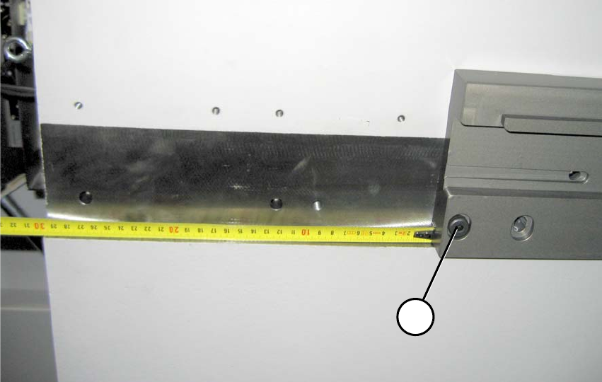
: Position the slide-in framework in the machine fram
e about 30 cm away from the front edge.
1b
1a
2
Fig. 2.11.1 1-gantry placement area: Distance to front edge about 30 cm (FS 02)
1-gantry placement area: 2
(1a) Reamed bolt (note position) 2
(2a) Bolts 2