00193897-0302_AI_MTC2+BE_DE+EN.pdf - 第127页
2b 2b 1b 2a 1a 2a 2a 2a 2a Assembly instructions MTC2 and Component docking unit on SIPLACE HF and X-series Edition 07/2009 125 2 Fig. 2.1 1.2 1- gantry placement area: Fixi ng inside with protective cover fitted 2 Fig. …
Assembly instructions MTC2 and Component docking unit on SIPLACE HF and X-series
Edition 07/2009
124
: Place the slide-in framework in the machine with care.
2
The slide-in framework must subsequently be pushed into the correct position and fixed
(see description below): 2
Photos of installation in location 2/4 in 1-ga
ntry placement area 2
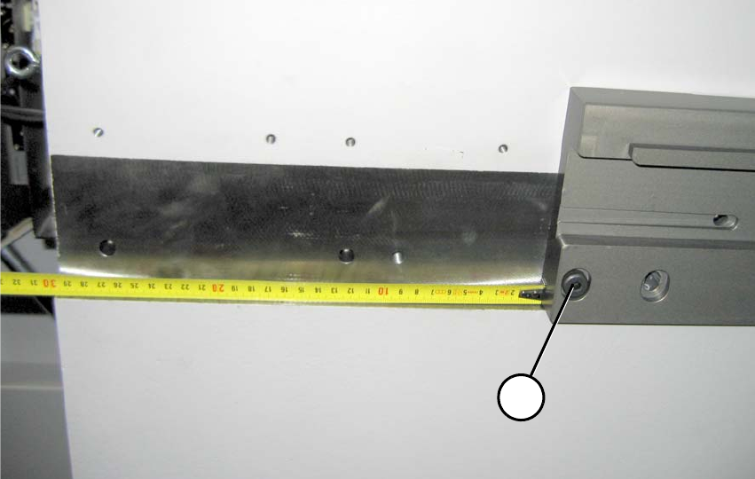
: Position the slide-in framework in the machine fram
e about 30 cm away from the front edge.
1b
1a
2
Fig. 2.11.1 1-gantry placement area: Distance to front edge about 30 cm (FS 02)
1-gantry placement area: 2
(1a) Reamed bolt (note position) 2
(2a) Bolts 2
2b
2b
1b
2a
1a
2a
2a
2a
2a
Assembly instructions MTC2 and Component docking unit on SIPLACE HF and X-series
Edition 07/2009
125
2
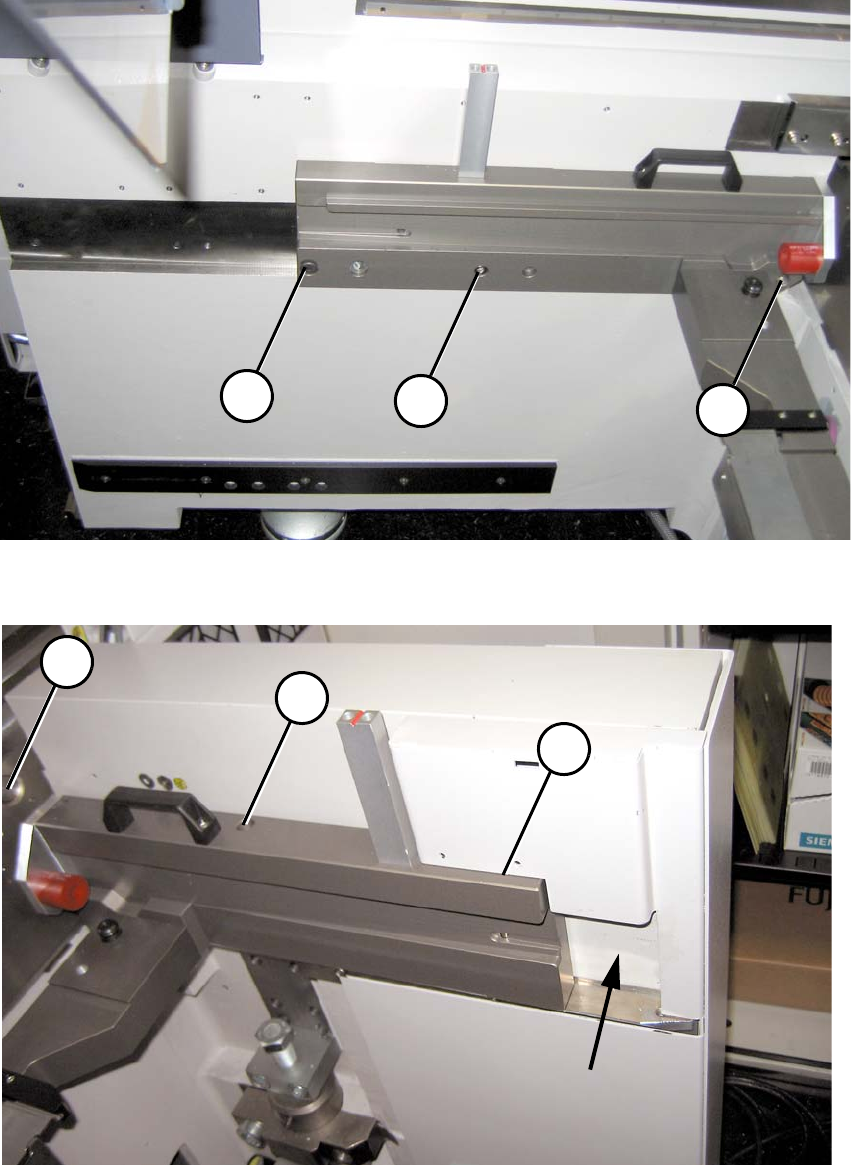
Fig. 2.11.2 1-gantry placement area: Fixing inside with protective cover fitted
2
Fig. 2.11.3 1-gantry placement area: Fixing outside with protective cover fitted
Assembly instructions MTC2 and Component docking unit on SIPLACE HF and X-series
Edition 07/2009
126
Photos of installation in location 2/4 in 2-gantry placement area 2
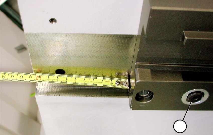
: Position the slide-in framework in the machine fram
e about 11 cm away from the front edge.
1a
1b
2
Fig. 2.11.4 2-gantry placement area: Distance to front edge about 11 cm
2-gantry placement area: 2
(1b) Reamed bolt (note position) 2
(2b) Bolts 2