00193897-0302_AI_MTC2+BE_DE+EN.pdf - 第135页
Assembly instructions MTC2 and Component docking unit on SIPLACE HF and X-series Edition 07/2009 133 2.12 Docking of the MTC2 : Check the height of the MTC2. It must have the same height as the place ment machine. 2 The …
Assembly instructions MTC2 and Component docking unit on SIPLACE HF and X-series
Edition 07/2009
132
: Route the cable in the cable duct and push the long cable back into the machine frame.
3
B
A
4
5
BB
AA
B
A
B
A
B
A
B
A
Brücke
zu SIPLACE
B
A
XS_Sicherheitsschleife_Siplace2
XS_Sicherheitsschleife_Meldung_Ausgang
XS_Sicherheitsschleife_Meldung_Eingang
XS_Sicherheitsschleife_MTC2
XS_Sicherheitsschleife_MTC1
ws
/4.7
/4.7
/4.7
/4.7
/4.7
ws
sw
br
gr
rt
bl
XS_Sicherheitsschleife_Siplace1
/4.7
NYSYÖ-J 7x1.0mm²
-W035
Wago 12-polig, Stift
zu SIPLACE
3
4
5
6
7
8
9
A
B
6
4
3
B
A
B
A
5
B
A
B
A
8
7
B
A
B
A
B
A
9
B
A
10
A
B
2
A
B
A
B
6
-XS_ODU.3
B
Feld 3
1
8
BB
7
AA
BB
9
AA
B
A
B
A
B
2
A
B
Wago 12-polig, Stift
-X1*2
A
B
AA
BB
A
BBB
AA
A
B
A
B
2
br
Feld 1
-XS_ODU_1
CAN-Bus
-X1*6
B BA BA AA B B
D_SUB 9-polig, Buchse
CANH
=SIPLACE
-X1*6
GND CANL GND
=SIPLACE
-X1*5
D_SUB 9-polig, Stift
A
Stellplatzkodierung
Schirm
A
B
A
-XS_ODU_2
1
Feld 2
B
A
CAN_GND1_SIPLACE
CAN_H_SIPLACE
CAN_GND2_SIPLACE
CAN_L_SIPLACE
CAN_SHLD1_SIPLACE
-XS_ODU
/18.8
/18.8
/18.8
/18.8
/18.8
0,25 mm²
0,25 mm²
0,25 mm²
br
-W025
ge
ws
0,25 mm²
0,00 mm²
gn
Schirm
LiYY 4x0,34mm²
-W030
gn
ADR0_1
/18.8
ADR1_1
ADR_GND
/18.8
/18.8
Sicherheitsschleife
A
B
10
12
-X112
=SIPLACE
BBB
AAA
11
AA
BB
10
A
-X1*5
A
B
A
B
B
A
B
A
A
B
A
B
A
B
A
B
B
A
B
A
B
A
2
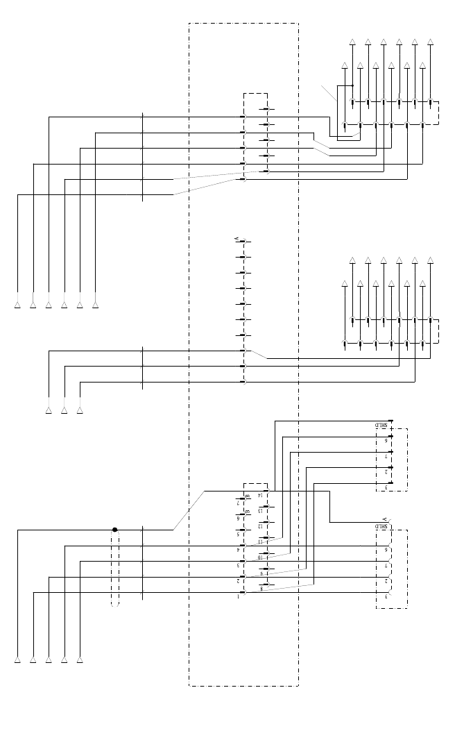
Fig. 2.11.11 Circuit diagram slide-in framework MTC2
Assembly instructions MTC2 and Component docking unit on SIPLACE HF and X-series
Edition 07/2009
133
2.12 Docking of the MTC2
: Check the height of the MTC2.
It must have the same height as the place
ment machine.
2
The height is indicated in the small window below the cover under the door of tower 1
(830 / 900 / 930 / 950 ± 15 mm).
2
: If it does not have the same height as the placement machine, adjust the MTC to the machine
height and then dock it to the machine.
2
For further information, see operating instructions of MTC2:
00193634- Operating instructions SIPLACE MTC2
00193635- User Manual SIPLACE MTC2 2
2
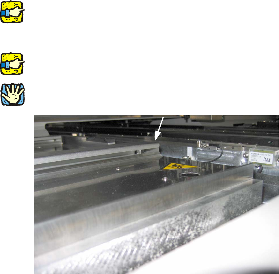
The MTC must not be higher than the clamping edges of the PCB conveyor. 2
2
2
Fig. 2.12.1 The height of the MTC must be adjusted to the PCB conveyor.
2
2
2
Assembly instructions MTC2 and Component docking unit on SIPLACE HF and X-series
Edition 07/2009
134
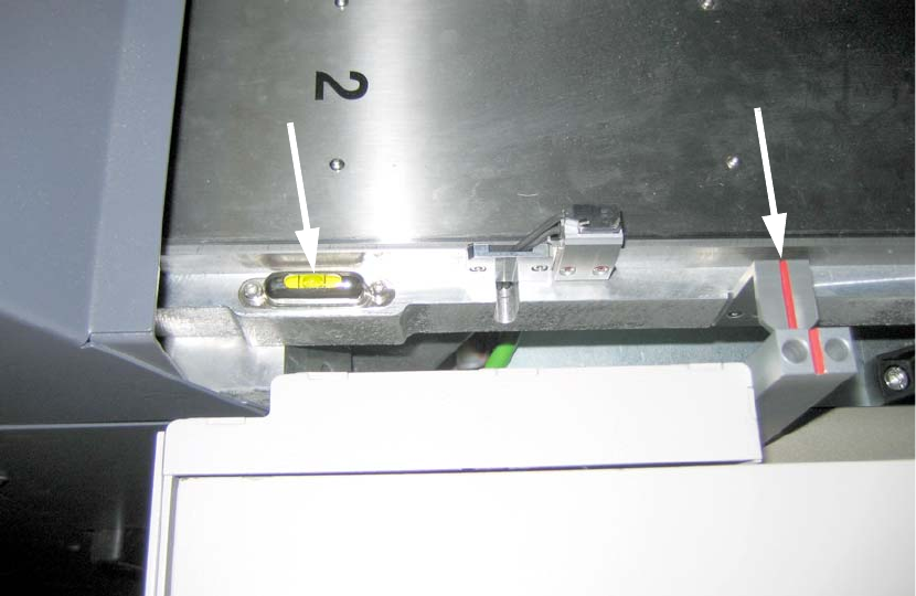
: Check for horizontal alignment on the MTC with a spirit level.
2
Fig. 2.12.2 Top view: MTC alignment
2
: Secure the MTC in the machine.
2
2
2
2