00193897-0302_AI_MTC2+BE_DE+EN.pdf - 第75页
Assembly instructions MTC2 and Component docking unit on SIPLACE HF and X-series Edition 07/2009 73 2 MTC2 and component docking unit on SIPLACE HF and X-series 2.1 Functional description These instructions cont ain a de…
X113
12
11
10
9
8
7
2
4
6
5
3
1
X3ra
9
8
7
2
4
6
5
3
1
12
11
10
X143
7
9
8
6
5
4
3
1
2
X54
6
5
4
3
1
2
n.b.
X14ra
3
5
6
4
2
1
n.b.
9
X18ra
4
8
7
6
5
2
3
1
9
4
8
7
6
5
2
3
X23ra
1
rt
bl
gr&rs
gn&ge
ws
br
gr&rs
gn&ge
rt
bl
ws&br
NOTHALT-Schleife1
NOTHALT-Schleife2
M_Haube
GND
(Kabel)
+24V
03002540-xx
(Kabel)
GND
03002542-xx
03002547-xx
GND
(Kabel)
+24V
+24V
NOTHALT-Schleife2
NOTHALT-Schleife1
NOTHALT-Schleife1
NOTHALT-Schleife2
gnge&1
gnge&1
2&3
4
5
6
7
8
9
10
11
n.b.
n.b.
2&3
4
5
6
7
8
9
10
11
n.b.
n.b.
M_Klappe
M_Klappe
M_BE-Tisch1
M_BE-Tisch4
X13ra_3
Zum Stecker
or
X1ra_24V
+24V
sw
X1ra_Haube
X1ra_0V
GND
sw
sw
ws
sw
ws
or
X1ra_0V
GND
X1ra_24V
+24V
sw
sw
X1ra_24V
X1ra_0V
+24V
GND
or
ws
sw
n.b.
sw
n.b.
n.b.
sw
M_Klappe sw
sw
n.b.
n.b.
n.b.
X1ra_Vin(+)Beleuchtung
X1ra_0V
Haube 4
Haubenschalter
1321
-
1422
03006476-xx
(Kabel)
+
gr
(W2)
(W2)ws
(W1)
(W1)1
2
(W1)
(W2)br
4
5(W1)
(W1)6
(W1)
(W1)7
8
(W2)ge
(W1)
(W1)9
10
(W1)11
(W1)
(W2)gn
3
X21h
1
2
X11f
1
2
3
4
sw
BE-Wagen Einzug
Stellplatz 1
Adapterstecker
BE-Klappe
03006496
X110
E29/30
B29/30
C29/30
D29/30
sw
rt
Stellplatz 1
BE-Wagen
(Kabel)
03006858-W1/W2
+24V
GND
11 (W1)
gn
3(W1)
(W2)
10
9
(W1)
(W1)
Stellplatz 4
BE-Wagen
E29/30
D29/30 rt
swB29/30
C29/30
X140
5(W1)
ge
8
(W2)
(W1)
6
7
(W1)
(W1)
br
4(W1)
(W2)
ws
2
(W2)
(W1)
X14f
4
3
2
1
sw
03006496
Adapterstecker
BE-Klappe
gr
1(W1)
(W2)
03006858-W1/W2
(Kabel)
BE-Wagen Einzug
Stellplatz 4
GND
+24V
2
1
X24h
ws
gr
Unterverteiler
03001532 (ra)
NOTHALT-SchleifeMTC4out
NOTHALT-SchleifeMTC4in
M_NOTHALT-TasteMTC
ws
sw
sw
X1ra_Klappe
M_NOTHALT-TasteMTC
X4rb_8(DI15)
CAN-E/A-Modul
M_Klappe
X1ra_Klappe
M_Haube
n.b.
n.b.
n.b.
n.b.
2
1
1
2
X18_7
X18_9
Stromversorgung
00354626-xx
03002506-W5
(Kabel)
GND
X1ra_0V
ws
9
9
8
sw
n.b.
M_NOTHALT-Taste
M_StartTaste
M_StoppTaste
M_Klappe
M_Haube
3
sw
5
7
6
4
sw
sw
sw
sw
2
1
X73ra
sw
sw
NOTHALT-SchleifeMTC4in
NOTHALT-SchleifeMTC4out
NOTHALT-SchleifeAusgang
X15ra_1
NOTHALT-TasteMTCsw
2
6
5
3
4
n.b.
sw
sw
sw
1
X72ra
sw
+5V
rs
1
SpannungBeleuchtungA
SpannungBeleuchtungB
SpannungGurtschneider
X1ra_5V
X1ra_0V
X1ra_24V
X1ra_0V
n.b.
7
8
6
gr
gr
sw
3
5
4
2
+24V
or
GND
ws
GND
ws
X71ra
gn&ge (W3)
1(W1)
2(W3)
3(W3)
1(W3)
1(W2)
2(W2)
2(W1)
(W2)
(W2)
(W2)
(W1)
(W1)
(W1)
br
gn
br
ws
gn
ws
rt
gn
ge
gr
rs
gn
br
ws
Main Distributor
Zum Stecker X73qa
03003221-xx
(Blatt 3)
(Kabel)
NOTHALT-SchleifeOK
X1ra_StartTaste
X1ra_NOTHALT-Taste
X1ra_StoppTaste
X1ra_Klappe
X1ra_Haube
M_BE-Tisch1
M_BE-Tisch4
X3rb_1(DI0)
CAN-E/A-Modul
(Kabel)
(Blatt 3)
03002520-W1/W2
Zum Stecker X72qa
Main Distributor
SchleifeAbwurfBehälter
X2rc_7
X2rc_9
X17ra_4
(VbelB)
(VbelA)
03002519-W1/W2/W3
(Kabel)
Main Distributor
(Blatt 3)
Zum Stecker X71qa
(Blatt 5)
(Blatt 5)
(Blatt 5)
(Blatt 5)
(Blatt 5)
(Blatt 5)
(Blatt 5)
(Blatt 5)
(Blatt 5)
sw
sw
3
3
Siehe Seite 4-7
Siehe Seite 3-7
Montageanleitung MTC2 und BE-Wageneinzug an SIPLACE HF und X-Serie
Ausgabe 07/2009
72
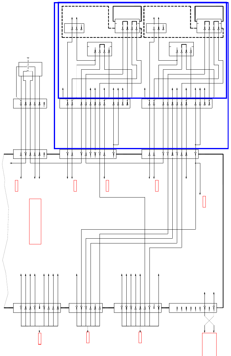
1
Abb. 1.13.2 Stromlaufplan

Assembly instructions MTC2 and Component docking unit on SIPLACE HF and X-series
Edition 07/2009
73
2 MTC2 and component docking unit
on SIPLACE HF and X-series
2.1 Functional description
These instructions contain a description of the installation of the component trolley (docking unit)
and MTC2 (Matrix Tray Changer 2). 2
For disassembly of the MTC2 or component trolley (docking unit), the working step
s must be car-
ried out in reverse order. 2
It is assumed that no MTC or component trolley is docked. 2
2
2
For SIPLACE HF, only installation of the component trolley HF (S-tape feeders) or MTC2 is pos-
sible.
2
2
On X-series machines, instead of the MTC2, both the component table X (for X-tape feeders) as
well as the HF-series component trolley (for S-tape feeders) can be used.
2
2
Note head configuration:
If a change is made to the C&P20 head, only the comp
onent docking unit X-series can be used.2

Assembly instructions MTC2 and Component docking unit on SIPLACE HF and X-series
Edition 07/2009
74
2.2 Requirements
2
Component trolley for S-tape feeders:
This is not permitted in combination with a C&P20 head! Crash risk! 2
2
– MTC on a 1-gantry placement area:
The current MTC2 slide-in framework up to FS 02 can only be mounted at locations 2 and 4.
– MTC on a 2-gantry placement area:
This can only be mounted in the X-series with SW 60
3 and slide-in framework (03009963-) with
FS 03.
– MTC at a 1-gantry placement area:
The current MTC2 pull-out frames up to FS 02 can only be fitted at location 2 and 4.
– MTC at a 2-gantry placement area:
This can only be fitted in the X-series with software version 603 and pull-out frames
(
03009963-) with FS 03.
– The C&P 20 placement head cannot be used with the MTC.
– In the 1-gantry placement area with MTC, the head can o
nly be fitted in the top position. The
installation height is monitored during the head reference run.
– Crash risk: When
the CPP head is used with the MTC, the travel range must also be re-
stricted. You should therefore order 2x the extension for
the Y axis stop (item no.: 03075963-
01 "Adaptation, Y axis stop, MTC“).
– Cras
h risk: When the CPP head is used with the MTC, the "notched base“ positioning aid on
the pull-out frame of the MTC must also be replaced. You should therefore order 2 x item no.:
03010773-02 "Notched base“. The new notched base is 103 mm high.
A pull-out frame with the FS04 does not require further conversion.
– When the CPP head is used with the MTC, the crash ligh
t barriers on the MTC's feed axis must
be fitted in the bottom position. Read the "MTC2 on component trolley docking unit X-S" as-
sembly instructions (item no. 00194725-xx).
– If the CPP is in the high position in conjunction
with the MTC, the lowest pick-up height is 1.5
mm from the top edge of the PCB when the shortest nozzle (9 mm) is used. Interference edges
on the trays should also be taken into account.
– Software: None