00193897-0302_AI_MTC2+BE_DE+EN.pdf - 第84页
Assembly instructions MTC2 and Component docking unit on SIPLACE HF and X-se ries Edition 07/2009 82 : Mount the fit-up aid ( 2 ) on the fasteners ( 1 ) provided on the component docking unit. : Attach the lif ting devic…
00377312-xx
Retrofit kit interface comp
onent trolley HF
up to A001 left for location 1/3
00377313-xx
Retrofit kit interface comp
onent trolley HF
up to A001 right for location 2/4
Assembly instructions MTC2 and Component docking unit on SIPLACE HF and X-series
Edition 07/2009
81
2
Fig. 2.6.2 For installation in prepared machine (inside)
2
2
2
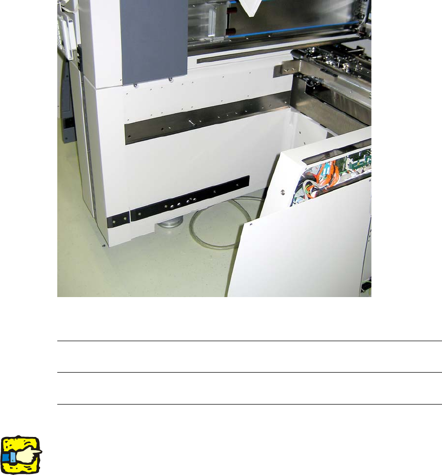
Prior to installation of the component docking unit, ensure that the tape cutter control PCB is
coded for the correct location (see jumper marking on control PCB). For further information, see
imprint on tape cutter control PCB. 2
2
2
2
2
2
2
2
Assembly instructions MTC2 and Component docking unit on SIPLACE HF and X-series
Edition 07/2009
82
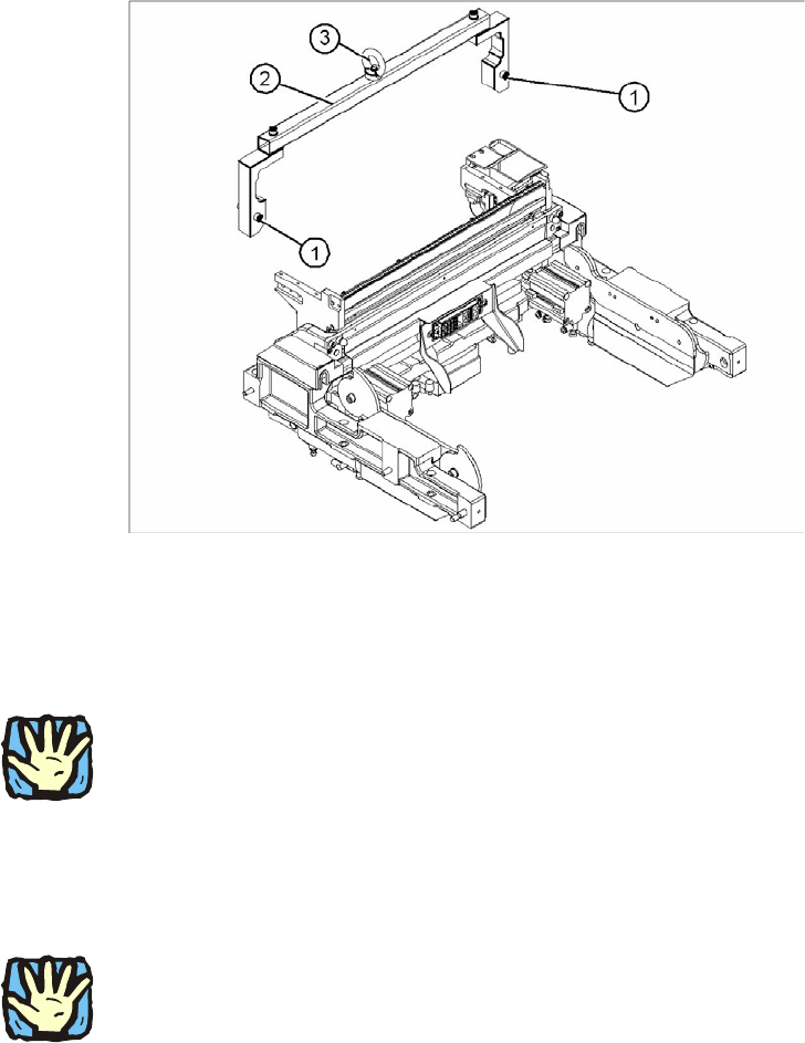
: Mount the fit-up aid (2) on the fasteners (1) provided on the component docking unit.
: Attach the lifting device to the eye (3) of the fit-
up aid (2).
2
Legend 2
1. Fixing
2. Fit-up aid f. carriage or entering /X-S (03015976-)
3. Eye
2
Heavy machine component:
The component docking unit is very heavy. For lifting purposes, the fit-up aid and suitable lifting
equipme
nt must be used (hand crane, etc.). 2
: Suitable gloves must be worn for lifting the component docking unit in position.
Gloves reduce the risk of cuts caused by the bla
de of the tape cutter.
2
2
Ensure that the cables and hoses are not damaged. 2
2
: Remove the fit-up aid.
2
2
2
2
Assembly instructions MTC2 and Component docking unit on SIPLACE HF and X-series
Edition 07/2009
83
2
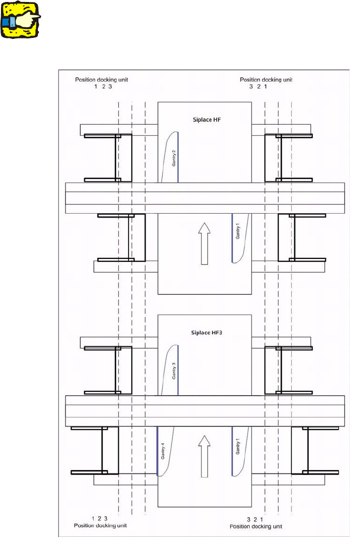
See diagram ‘Assembly positions according to machine type and location’.
2
: Push the component docking unit into the required position.
2
2
2
2