00193897-0302_AI_MTC2+BE_DE+EN.pdf - 第97页
00378461-xx Retrofit Kit C-O-Table Dock-In HF Assembly instructions MTC2 and Component docking unit on SIPLACE HF and X-series Edition 07/2009 95 2 2 2 Prior to installation of the comp onent docking un it, ensure that t…
Assembly instructions MTC2 and Component docking unit on SIPLACE HF and X-series
Edition 07/2009
94
2.7 Installation of component docking unit for S-tape
feeders on a SIPLACE HF (Series No. from A001),
X-series and D3
2
Crash risk:
This component docking unit in combination with a C&P2
0 head is not permitted!
2
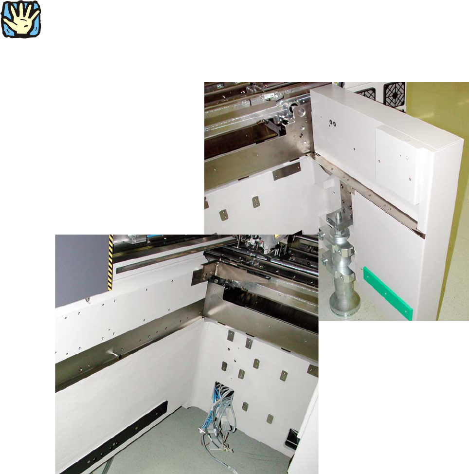
The machine has to look like this: 2
2
Fig. 2.7.1 For installation in prepared machine
00378461-xx Retrofit Kit C-O-Table Dock-In HF
Assembly instructions MTC2 and Component docking unit on SIPLACE HF and X-series
Edition 07/2009
95
2
2
2
Prior to installation of the component docking unit, ensure that the tape cutter control PCB is
coded for the correct location (see jumper marking on control PCB). For further information, see
imprint on tape cutter control PCB. 2
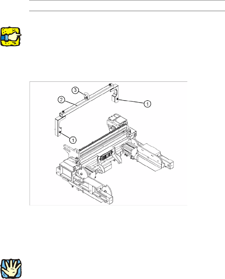
: Mount the fit-up aid (2) on
the fasteners (1) provided on the component docking unit.
: Attach the lifting device to the eye (3) of the fit-up
aid (2).
2
Legend 2
1. Fixing
2. Fit-up aid f. carriage or entering /X-S (03015976-)
3. Eye
2
2
Heavy machine component:
The component docking unit is very heavy. For lifting purp
oses, the fit-up aid and suitable lifting
equipment must be used (hand crane, etc.). 2
Suitable gloves must be worn for lifting the compone
nt docking unit in position.
Gloves reduce the risk of cuts caused
by the blade of the tape cutter. 2
2
2
Assembly instructions MTC2 and Component docking unit on SIPLACE HF and X-series
Edition 07/2009
96
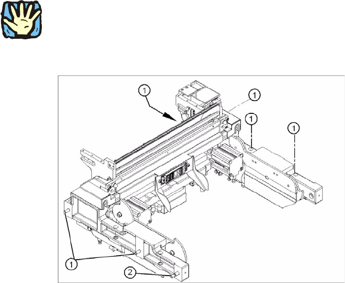
: Lift the component docking unit in the machine with the aid of the lifting device.
2
Ensure that the cables and hoses are not damaged. 2
2
: Remove the fit-up aid.
2
2
: Push the component docking unit into the correct position. See diagram ‘Assembly positions
according to machine type and location’.
2
2