00193897-0302_AI_MTC2+BE_DE+EN.pdf - 第99页
Assembly instructions MTC2 and Component docking unit on SIPLACE HF and X-series Edition 07/2009 97 2 Fig. 2.7.2 Position of docking unit frame
Assembly instructions MTC2 and Component docking unit on SIPLACE HF and X-series
Edition 07/2009
96
: Lift the component docking unit in the machine with the aid of the lifting device.
2
Ensure that the cables and hoses are not damaged. 2
2
: Remove the fit-up aid.
2
2
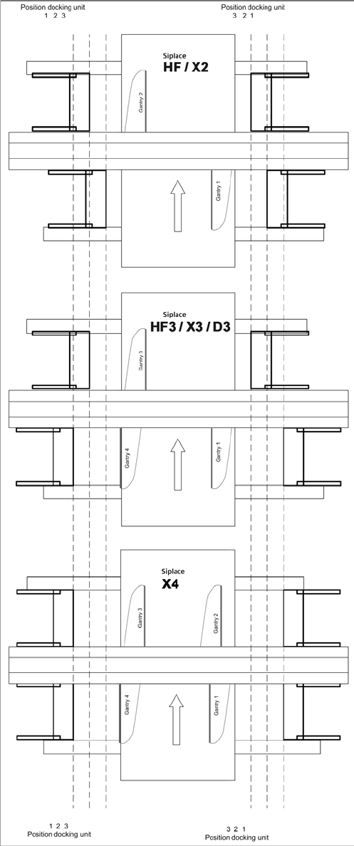
: Push the component docking unit into the correct position. See diagram ‘Assembly positions
according to machine type and location’.
2
2
Assembly instructions MTC2 and Component docking unit on SIPLACE HF and X-series
Edition 07/2009
97
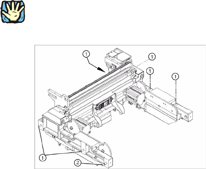
2
Fig. 2.7.2 Position of docking unit frame

Assembly instructions MTC2 and Component docking unit on SIPLACE HF and X-series
Edition 07/2009
98
2
Observe sequence:
The reamed bolt must be tightened first and then th
e other fixing bolts. This ensures correct sea-
ting of the docking unit framework. 2
: Screw in the reamed bolt and then the fixing bolts without tightening.
: First tighten the reamed bolt, then the fixing bolt
s on the inside of the machine and then those
on the outside of the machine.
2
: Re-establish all electrical connections.
: Connect compressed-air lines to the compressed-air connectors.
2