00197733-01_VD_605_04_DE_EN.pdf - 第22页
Station Software 60 5.04 / Version D escription Ausgabe 04/ 2015 Edition 22 7.3 Co mponent Ra nge Component r ange for C& P20 hea d With standar d type 23 compo nent camera (C&P 6 x 6 digital ) 01005 through 2220…
Station Software 605.04 / Version Description Ausgabe 04/2015 Edition
21
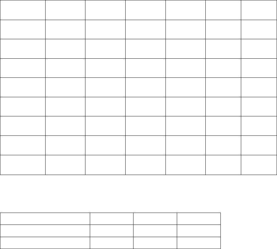
7.2 Digital Camera Systems
Digital CCD cameras are used as the camera systems.
7.2.1 Component Cameras
All heads are equipped with the standard cameras listed below. High-resolution cameras are
additionally available for the Twin Head, the P&P module and the 12-segment C&P head.
Component
camera
Camera
type
6-seg.
C&P head
12-seg
C&P head
C&P20
head
Twin
Head
P&P
module
C&P
6 x 6 digital
23
- -
(Default) -
-
C&P
18 x 18 digital
28
-
(Default) - -
-
C&P
27 x 27 digital
29
(optional)
(optional) - -
-
C&P
27 x 27 digital
30
(Default)
(optional) - -
-
C&P
16 x 16 digital
38
-
(optional) - -
-
Stat. P&P
55 x 45 digital
33
- - - (Default)
(optional)
Stat. P&P
16 x 16 digital
25
- - - (optional)
(optional)
Stat. P&P
32 x 32 digital
36
- - - -
(Default)
Table 7-1: Component cameras
7.2.2 PCB Cameras
PCB camera Camera type X-series D-series
28 digital 34
(Default)
(Default)
Multicolor 28 digital 24
(optional) -
Table 7-2: PCB cameras

Station Software 605.04 / Version Description Ausgabe 04/2015 Edition
22
7.3 Component Range
Component range for C&P20 head With standard type 23 component
camera
(C&P 6 x 6 digital)
01005 through 2220, Melf, SOT,
SOD
Component specification
max. Höhe ax height 4 mm
Min. lead pitch 0.25 mm
Min. ball pitch 0.4 mm
Min. ball diameter 0.2 mm
Min. dimensions 0.18 x 0.18 mm
Max. dimensions 6 x 6 mm (including component
tolerances)
Max. weight 1 g
Programmable placement force,
selectable level
1.5 ± 0.5 N
2.0 ± 0.5 N
3.5 ± 1 N
4.5 ± 1 N
Nozzle types 10 xx, 11 xx, 12 xx
Table 7-3: Component range for C&P20 head
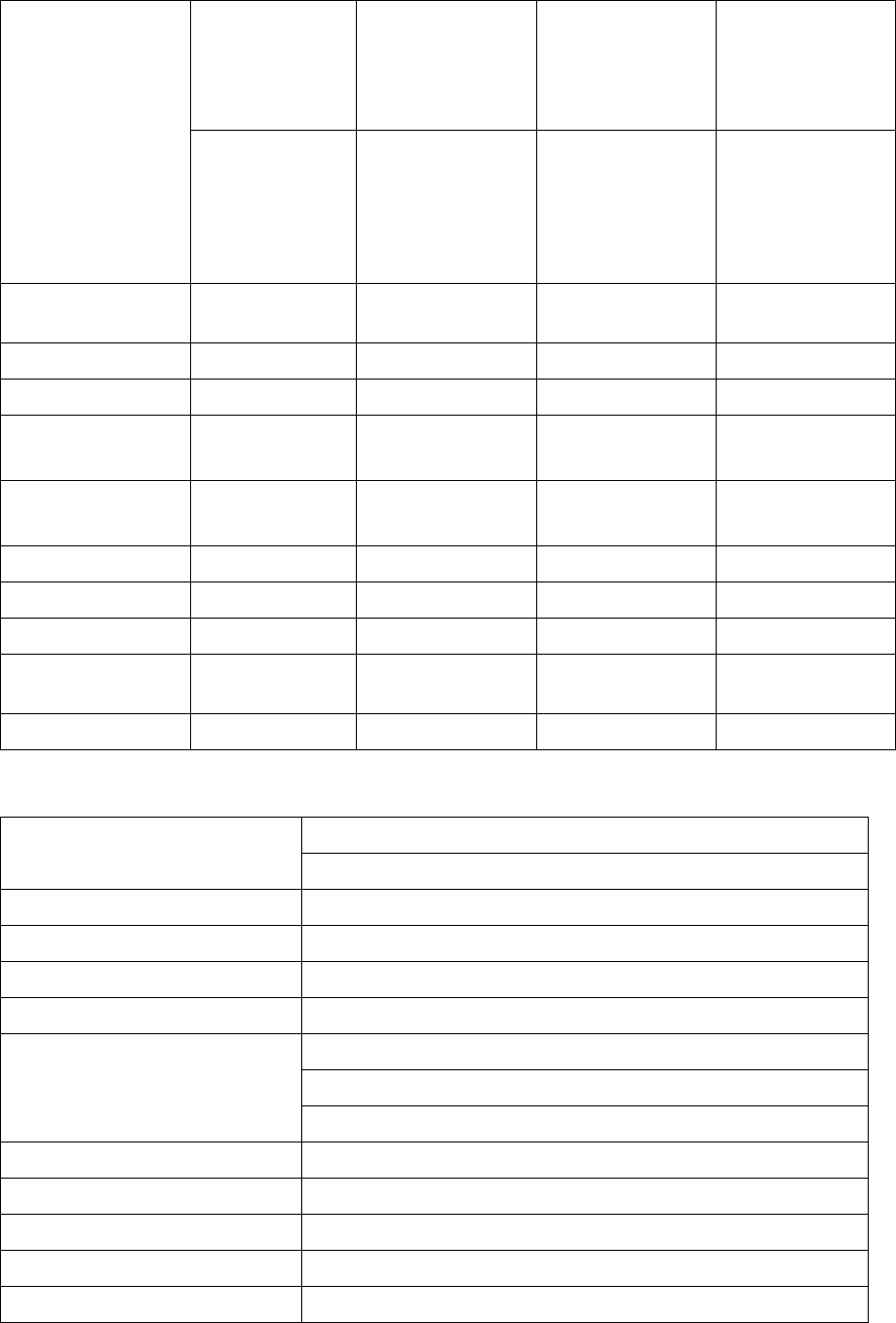
Station Software 605.04 / Version Description Ausgabe 04/2015 Edition
23
Component range
for C&P12 head
With standard
component
camera
C&P (type 28)
18 x 18, digital
With high-resolution
component camera
C&P (type 29)
27 x 27, digital
With high-resolution
component camera
C&P (type 30)
27 x 27, digital
With high-resolution
component camera
C&P (type 38)
16 x 16, digital
0402 through
PLCC44, BGA,
µBGA, flip-chip,
TSOP, QFP, SO
through SO32,
DRAM
0201 through
PLCC44, bare die,
BGA, µBGA, flip-
chip, TSOP, QFP,
SO through SO32,
DRAM
01005 through
PLCC, SO, QFP,
TSDP, SOT, MELF,
CHIP, IC, BGA
01005 through
PLCC44, bare die,
BGA, µBGA, flip-
chip, TSOP, QFP,
SO through SO32,
DRAM
Component
specification
Max height 6 mm 6 mm 6 mm 6 mm
Min. lead pitc 0.5 mm 0.3 mm 0.3 mm 0.25 mm
Min. ball pitch 0.45 mm 0.25 mm 0.25 mm < 18 x 18
0.35 mm ≥ 18 x 18
0.25 mm
Min. ball diameter 0.25 mm 0.14 mm 0.14 mm < 18 x 18
0.2 mm ≥ 18 x 18
0.14 mm
Min. dimensions 0.5 x 0.5 mm 0.3 x 0.3 mm 0.18 x 0.18 mm 0.18 x 0.18 mm
Max. dimensions 18.7 x 18.7 mm 18.7 x 18.7 mm 18.7 x 18.7 mm 16 x 16 mm
Max. weight 2 g 2 g 2 g 2 g
Programmable
placement force
2.4 N - 5 N 2.4 N - 5 N 2.4 N - 5 N 2.4 N - 5 N
Nozzle types 9 xx 9 xx 9 xx 9 xx
Table 7-4: Component range for C&P12 head
Component range for C&P6 head With high-resolution type 29 component camera (C&P 27 x 27 digital)
0201 through 27 x 27 mm
Component specification
Max height 8.5 mm
Min. lead pitch 0.3 mm
Min. ball pitch 0.25 mm für BE < 18 x 18 mm
Min. ball diameter
0.35 mm für BE ≥ 18 x 18 mm
0.14 mm für BE < 18 x 18 mm
0.2 mm für BE ≥ 18 x 18 mm
Min. dimensions 0.3 x 0.3 mm
Max. dimensions 27 x 27 mm
Max. weight 5 g
Programmable placement force 2.4 N - 5,0 N
Nozzle types 8 xx, 9 xx
Table 7-5: Component range for C&P6 head