00197733-01_VD_605_04_DE_EN.pdf - 第23页
Station Software 60 5.04 / Version D escription Ausgabe 04/ 2015 Edition 23 Component r ange for C&P 12 head With standard component camera C&P ( typ e 28) 18 x 18, digital With high - resol ution component ca me…
Station Software 605.04 / Version Description Ausgabe 04/2015 Edition
22
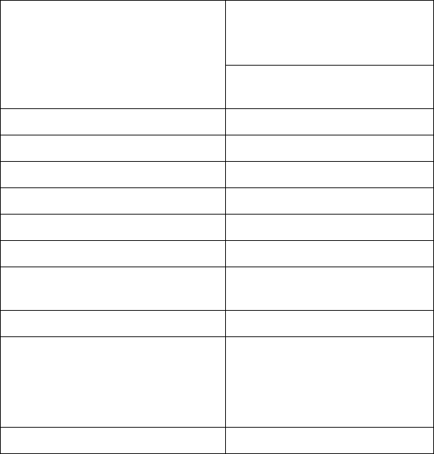
7.3 Component Range
Component range for C&P20 head With standard type 23 component
camera
(C&P 6 x 6 digital)
01005 through 2220, Melf, SOT,
SOD
Component specification
max. Höhe ax height 4 mm
Min. lead pitch 0.25 mm
Min. ball pitch 0.4 mm
Min. ball diameter 0.2 mm
Min. dimensions 0.18 x 0.18 mm
Max. dimensions 6 x 6 mm (including component
tolerances)
Max. weight 1 g
Programmable placement force,
selectable level
1.5 ± 0.5 N
2.0 ± 0.5 N
3.5 ± 1 N
4.5 ± 1 N
Nozzle types 10 xx, 11 xx, 12 xx
Table 7-3: Component range for C&P20 head
Station Software 605.04 / Version Description Ausgabe 04/2015 Edition
23
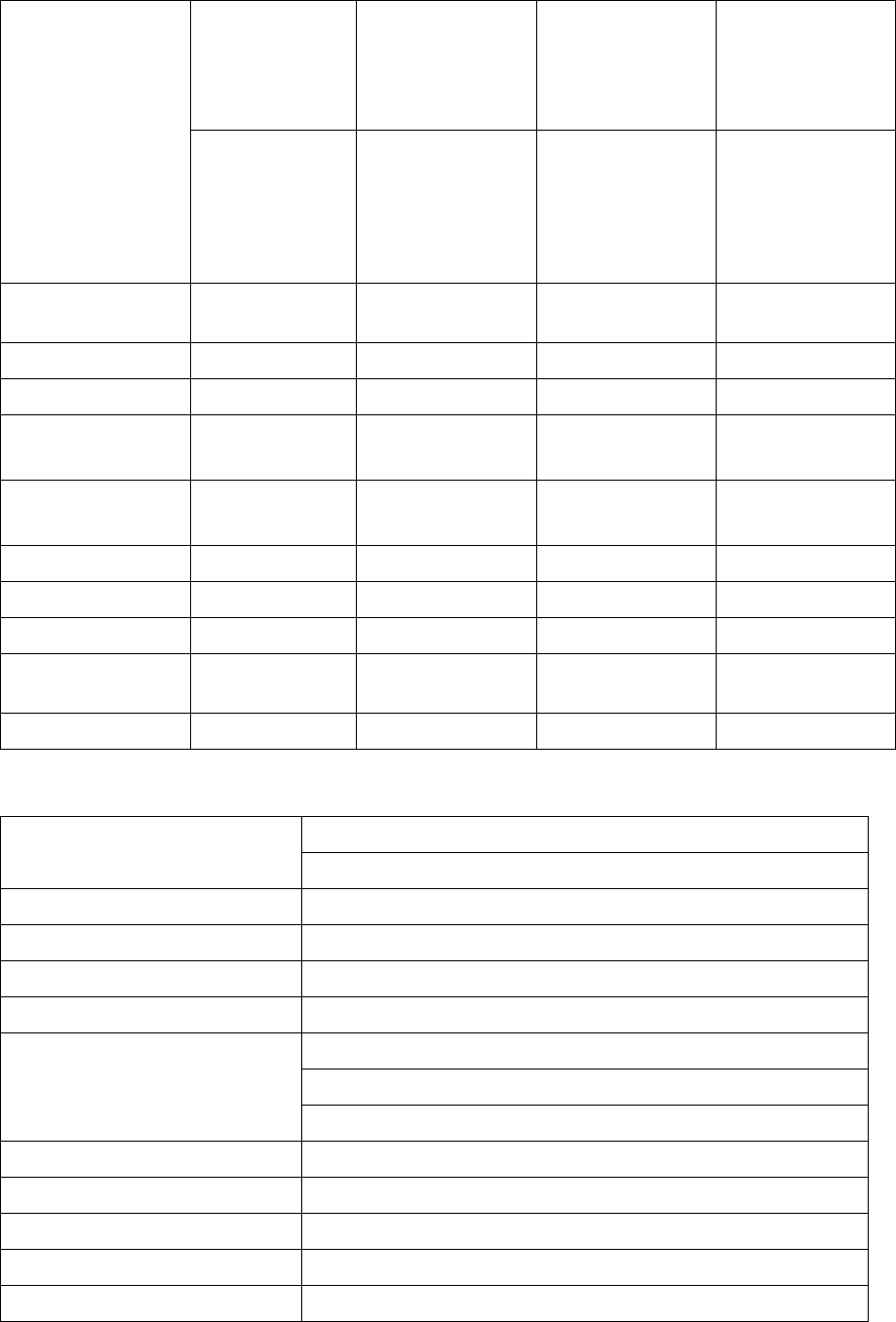
Component range
for C&P12 head
With standard
component
camera
C&P (type 28)
18 x 18, digital
With high-resolution
component camera
C&P (type 29)
27 x 27, digital
With high-resolution
component camera
C&P (type 30)
27 x 27, digital
With high-resolution
component camera
C&P (type 38)
16 x 16, digital
0402 through
PLCC44, BGA,
µBGA, flip-chip,
TSOP, QFP, SO
through SO32,
DRAM
0201 through
PLCC44, bare die,
BGA, µBGA, flip-
chip, TSOP, QFP,
SO through SO32,
DRAM
01005 through
PLCC, SO, QFP,
TSDP, SOT, MELF,
CHIP, IC, BGA
01005 through
PLCC44, bare die,
BGA, µBGA, flip-
chip, TSOP, QFP,
SO through SO32,
DRAM
Component
specification
Max height 6 mm 6 mm 6 mm 6 mm
Min. lead pitc 0.5 mm 0.3 mm 0.3 mm 0.25 mm
Min. ball pitch 0.45 mm 0.25 mm 0.25 mm < 18 x 18
0.35 mm ≥ 18 x 18
0.25 mm
Min. ball diameter 0.25 mm 0.14 mm 0.14 mm < 18 x 18
0.2 mm ≥ 18 x 18
0.14 mm
Min. dimensions 0.5 x 0.5 mm 0.3 x 0.3 mm 0.18 x 0.18 mm 0.18 x 0.18 mm
Max. dimensions 18.7 x 18.7 mm 18.7 x 18.7 mm 18.7 x 18.7 mm 16 x 16 mm
Max. weight 2 g 2 g 2 g 2 g
Programmable
placement force
2.4 N - 5 N 2.4 N - 5 N 2.4 N - 5 N 2.4 N - 5 N
Nozzle types 9 xx 9 xx 9 xx 9 xx
Table 7-4: Component range for C&P12 head
Component range for C&P6 head With high-resolution type 29 component camera (C&P 27 x 27 digital)
0201 through 27 x 27 mm
Component specification
Max height 8.5 mm
Min. lead pitch 0.3 mm
Min. ball pitch 0.25 mm für BE < 18 x 18 mm
Min. ball diameter
0.35 mm für BE ≥ 18 x 18 mm
0.14 mm für BE < 18 x 18 mm
0.2 mm für BE ≥ 18 x 18 mm
Min. dimensions 0.3 x 0.3 mm
Max. dimensions 27 x 27 mm
Max. weight 5 g
Programmable placement force 2.4 N - 5,0 N
Nozzle types 8 xx, 9 xx
Table 7-5: Component range for C&P6 head
Station Software 605.04 / Version Description Ausgabe 04/2015 Edition
24
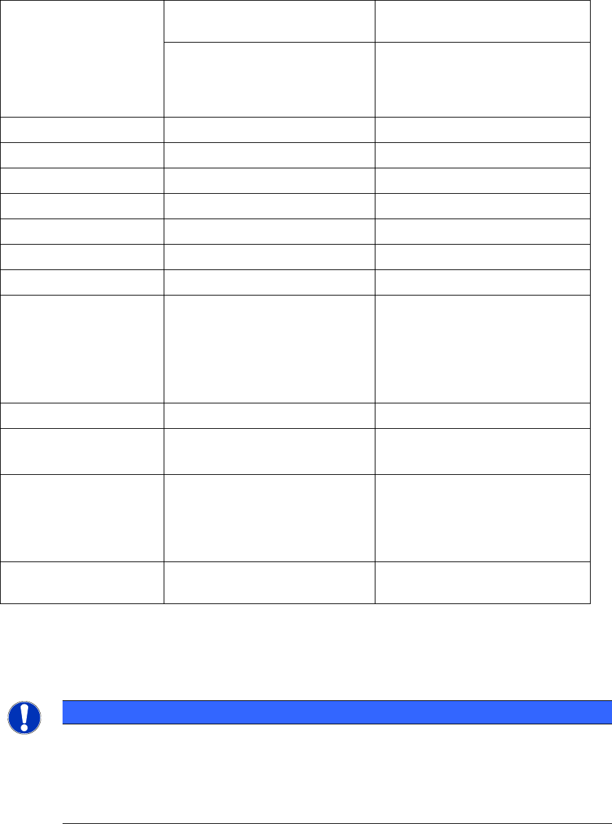
Component range for
Twin Head
With type 33 component camera
(Stat. P&P 55 x 45 digital)
With type 25 component camera
(Stat. P&P 16 x 16 digital)
0603 through SO, PLCC, QFP,
BGA, special components, bare
die, flip-chip
0201 through SO, PLCC, QFP,
sockets, connectors, BGA, special
components, bare die, flip-chip,
shield
Component specification
Max height 25 mm (higher on request) 25 mm (higher on request)
Min. lead pitch 0.3 mm 0.25 mm
Min. ball pitch 0.35 mm 0.14 mm
Min. ball diameter 0.2 mm 0.08 mm
Min. dimensions 0.5 x 0.5 mm 0.2 x 0.2 mm
Max. dimensions 55 x 45 mm (single measurement) 16 x 16 mm (single measurement)
When used with two nozzles
50 x 50 mm or 69 x 10 mm²
When used with one nozzle:
85 x 85 mm or 125 x 10 mm²
max. 200 x 125 mm (with
restrictions)
Max. weight 100 g
*)
100 g
*)
Programmable placement
force
1.0 N - 15 N
1.0 N - 30 N
**)
1.0 N - 15 N
1.0 N - 30 N
**)
Nozzle types 5 xx (standard)
4 xx + adapter
8 xx + adapter
9 xx + adapter
5 xx (standard)
4 xx + adapter
8 xx + adapter
9 xx + adapter
Distance between nozzles
on the two segments
70.80 mm 70.80 mm
Table 7-6: Component range for Twin Head
*)
If standard nozzles are used
**)
Valid for HFTH only
NOTICE for the 904 nozzle type:
For the 904 nozzle type the vacuum threshold value has been increased from 20% to
40%. For components drawing
more leak air due to their surface shapes, this may cause
a higher amount of error messages.
As workaround, it is possible to create a special nozzle in SIPLACE Pro, based on the
nozzle type 904, in which you enter lower vacuum values.