00197042-04_SM_X-Serie-S_Customer_EN.pdf - 第108页
4 Electrics and control system 4.2 BoxPC 108 Service Manual SIPLACE X-Serie S 06/2019 4.2.2 Overview of Connections for BoxPC 427D Fig.127: BoxPC 427D - connections 4.2.3 Overview of Connections for BoxPC 627x/827x Fig.…
4 Electrics and control system
4.2 BoxPC
Service Manual SIPLACE X-Serie S 06/2019 107
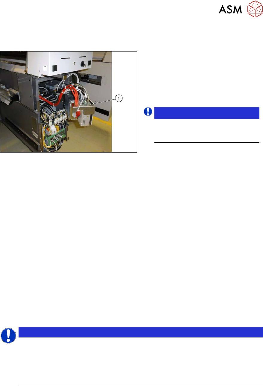
4.2.1.2 Replacing the BoxPC 427x
Overview
Fig.126: BoxPC in machine
1. BoxPC
The BoxPC is located behind the cover,
between locations 1 and 2.
See also: 4.2.2 "Overview of Connections for
BoxPC 427D" [}108]
NOTICE!
Conversion of a BoxPC 827C to a
BoxPC 427D is not possible.
.
Removal
► Back up the machine data.
► Switch off the machine, disconnect it from the power supply and secure it to prevent
unauthorized reactivation.
1.2 "Preparatory work..." [}16]
► Unplug all press-fit connections to the BoxPC. If necessary, mark their positions to make clear
assignment easier later on.
► Loosen the screws fastening the Box PC and remove it from the machine.
Installation
► Follow the removal instructions in reverse order for installation. Also observe the following
instructions:
●
If parts are missing in the new BoxPC (e.g. ethernet adapter, memory extension), take these
from the old BoxPC and use them in the new one.
4.2.5 "Replacing the CAN card (BoxPC 627B/827C only, up to no. Gxxxx)" [}109]
4.2.6 "Replacing the GigE Ethernet Adapter" [}109]
4.2.7 "Replacing the LAN card (from serial no. Hxxxx)" [}110]
4.2.8 "Replacing the Hotlink interface card" [}111]
4.2.9 "Replacing the RAM in the BoxPC" [}112]
NOTICE
Installing the BoxPC
► The BoxPC needs to be installed after it has been fitted. Read the relevant installation
guide.
► BIOS update and setting images are no longer included on the station software CD.
The CDs for the BIOS settings are only available via the SIPLACE Software Download
Center (SDC).
4 Electrics and control system
4.2 BoxPC
108 Service Manual SIPLACE X-Serie S 06/2019
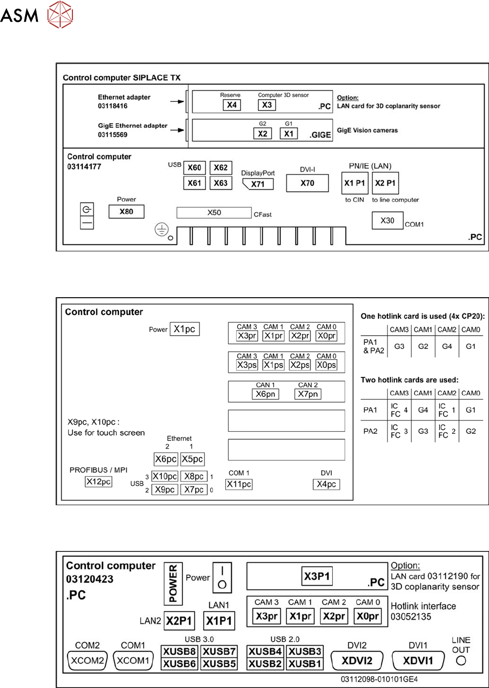
4.2.2 Overview of Connections for BoxPC 427D
Fig.127: BoxPC 427D - connections
4.2.3 Overview of Connections for BoxPC 627x/827x
Fig.128: Overview of connections for BoxPC 627x/827x
4.2.4 Overview of connections for BoxPC ABP402-A
Fig.129: Connections BoxPC ABP402-A CPU1020E 2xPCI SSD (iBase) [03120423-xx] (from Nxxxx onwards)
4 Electrics and control system
4.2 BoxPC
Service Manual SIPLACE X-Serie S 06/2019 109
4.2.5 Replacing the CAN card (BoxPC 627B/827C only, up to no. Gxxxx)
Parts, equipment and tools
●
CAN card COM168V2-PCI [03079973-xx] (old: [03052590-xx])
Removal
The CAN card is installed in the BoxPC.
► Switch off the machine, disconnect it from the power supply and secure it to prevent
unauthorized reactivation.
1.2 "Preparatory work..." [}16]
► Dismantle and remove the BoxPC from the machine.
4.2.1 "Replacing the Control Computer BoxPC" [}104]
► Remove the two screws fastening the cover of the BoxPC and open the cover.
► Remove the screw fastening the plug-in card and then remove this card.
Installation
► Follow the removal instructions in reverse order for installation. Also observe the following
instructions:
– Make sure that the plug-in card is correctly fitted into its slot.
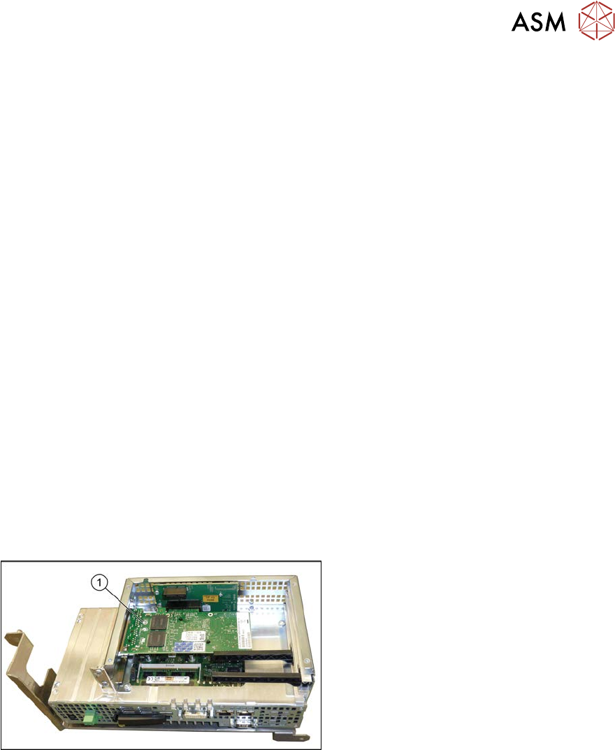
4.2.6 Replacing the GigE Ethernet Adapter
Parts, equipment and tools
●
GigE ethernet adapter PCI-E I340-T4 [03105575‑xx]
●
GigE-Ethernet-Adapter PCI-E I350 T2 V2 BLK [03115569‑xx]
Overview
Fig.130: GigE Ethernet adapter in the BoxPC 427D
1. GigE ethernet adapter
Removal
► Switch off the machine, disconnect it from the power supply and secure it to prevent
unauthorized reactivation.
1.2 "Preparatory work..." [}16]
► Dismantle and remove the BoxPC from the machine.
4.2.1 "Replacing the Control Computer BoxPC" [}104]
► Remove the screws fastening the cover of the BoxPC and open the cover.
► Remove the screw fastening the Ethernet adapter and remove the Ethernet adapter.
Installation
► Follow the removal instructions in reverse order for installation. Also observe the following
instructions:
– Make sure that the plug-in card is correctly fitted into its slot.