00197042-04_SM_X-Serie-S_Customer_EN.pdf - 第112页
4 Electrics and control system 4.2 BoxPC 112 Service Manual SIPLACE X-Serie S 06/2019 4.2.9 Replacing the RAM in the BoxPC Parts, equipment and tools NOTICE RAM Microsoft Windows 7/8 needs at least 2 GB RAM. Microsoft Wi…
4 Electrics and control system
4.2 BoxPC
Service Manual SIPLACE X-Serie S 06/2019 111
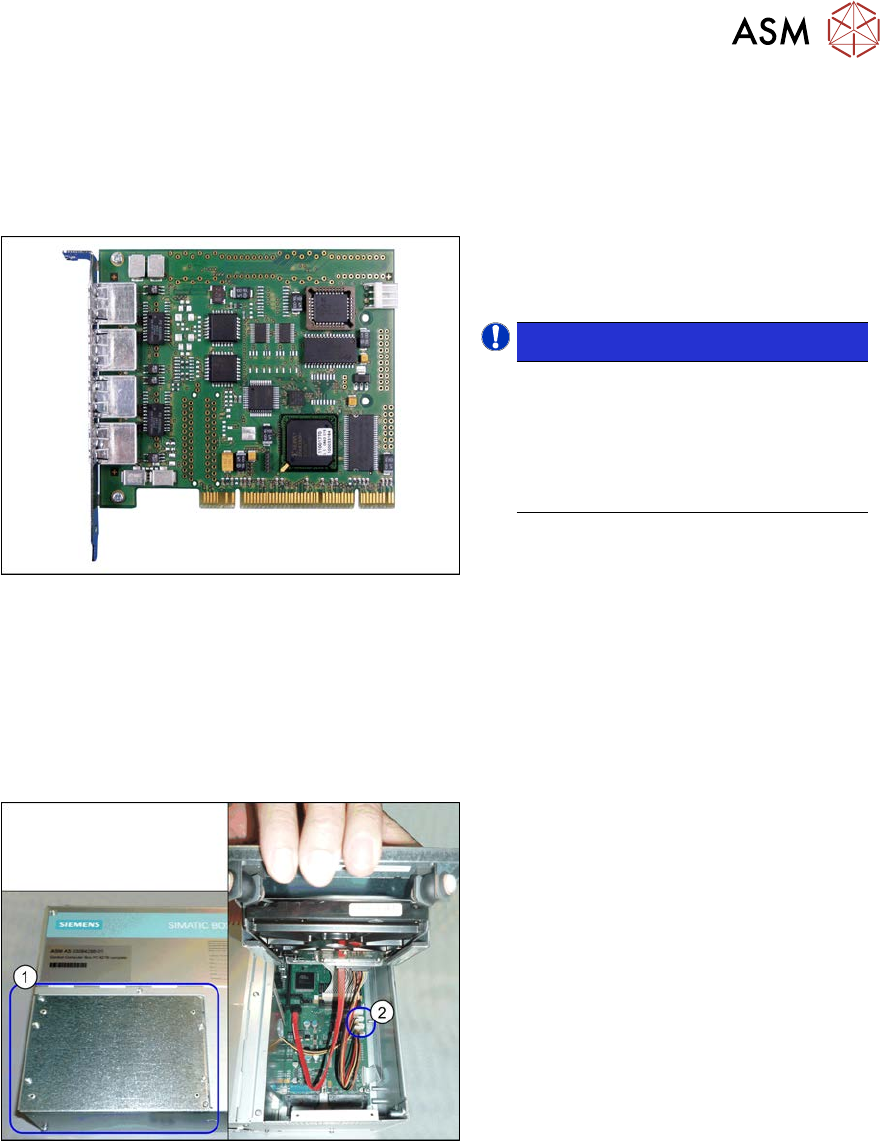
4.2.8 Replacing the Hotlink interface card
The hotlink interface is fitted in BoxPCs of type 627B/827C.
BoxPCs of this type are fitted in the SIPLACE X-Series S up to machine no. Gxxxx.
Parts, equipment and tools
Fig.132: Hotlink interface
●
Hotlink interface PCI-A24-K01
[03052135-xx]
NOTICE!
Hotlink interface power cable
The hotlink interface is supplied
without a hotlink interface power cable.
You may need to order the hotlink in-
terface power cable [03042074-xx]
separately.
.
Removal/installation
► Removal and installation of the hotlink interface is identical to that for the CAN card (see 4.2.5
"Replacing the CAN card (BoxPC 627B/827C only, up to no. Gxxxx)" [}109]). Also observe
the following instructions:
– Connect the "hotlink interface/power" cable [03042074-xx]. Follow the diagram below for
this.
Fig.133: Hotlink interface power cable (example of BoxPC
827 shown)
Hotlink cable
► If you are replacing the hotlink interface
power cable (2), you will need to loosen
and open the cover (1) on the hard
drives.
However, if you are continuing to use
the old hotlink interface power cable,
this step is not required.
4 Electrics and control system
4.2 BoxPC
112 Service Manual SIPLACE X-Serie S 06/2019
4.2.9 Replacing the RAM in the BoxPC
Parts, equipment and tools
NOTICE
RAM
Microsoft Windows 7/8 needs at least 2 GB RAM.
Microsoft Windows 10 needs 4 GB RAM.
Machine type PC type RAM module type
X-Series S up to no.:
Gxxxx, SX4/DX4
BoxPC 827C [03094732‑xx] Minimum 2GB DDR3 1066 DIMM *)
X-Series S from no.:
Hxxxx
BoxPC 427D [03114177Sxx] 4 GB DDR 1333Mhz PC3-10600 SO-
DIMM
*) For more information about the RAM needed, contact the SIPLACE hotline.
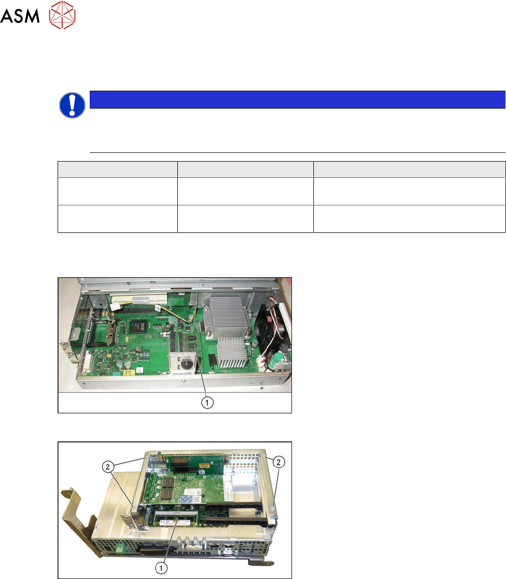
Overview
Fig.134: BoxPC 627B/C
1. Memory extension
Fig.135: BoxPC 427D
1. Memory extension
2. Four screws fastening the cover
Removal
► Switch off the machine, disconnect it from the power supply and secure it to prevent
unauthorized reactivation.
1.2 "Preparatory work..." [}16]
► Dismantle and remove the BoxPC from the machine.
4.2.1 "Replacing the Control Computer BoxPC" [}104]
► Remove the screws fastening the cover of the BoxPC and open the cover.
► Open the locks on both sides of the memory extension and remove the memory extension.
4 Electrics and control system
4.3 Replacing the cover fan
Service Manual SIPLACE X-Serie S 06/2019 113
Installation
► Follow the removal instructions in reverse order for installation. Also observe the following
instructions:
– Make sure that you insert the memory extension the right way round. The new memory ex-
tension must audibly engage into its slot.
4.3 Replacing the cover fan
Parts, equipment and tools
●
Fan cover 1-part [03052317‑xx] (replaces: [03091773-xx])
●
Sealing varnish Loctite 241 [02101037-xx]
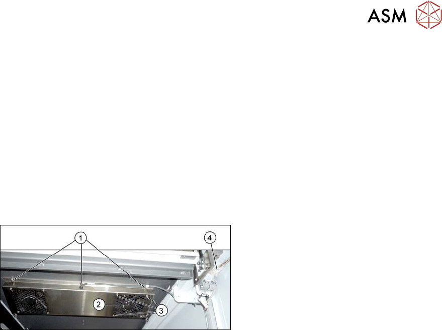
Overview
Fig.136: Overview of cover fan
1. Screws for fastening the cover plate
2. Cover fan
3. Fastening screws for cover fan
4. Connection cable for cover fan
Removal
► Switch off the machine, disconnect it from the power supply and secure it to prevent
unauthorized reactivation.
1.2 "Preparatory work..." [}16]
The fans are fastened to the cover plate, inside. First dismantle the cover plate:
► Unplug the connection cable(4).
► Remove the six screws (1) fastening the cover plate and remove the cover plate. Make sure
that the various washers are not lost. You may want to mark their positions, to make clear as-
signment easier later on.
► Remove the four screws (3) fastening the cover fan. Make sure that the washers are not lost.
► Unplug the cover fan connection cable and remove the cover fan from the machine.
Installation
► Follow the removal instructions in reverse order for installation. Also observe the following
instructions:
– When fitting the fan, note the correct direction of air flow. The fan must blow the air into the
machine. If necessary, you can use the adjacent fan as a guide. The flow of air is shown
by an arrow on the side of the fan housing.
– Secure the six screws fastening the cover plate with Loctite 241.