00197042-04_SM_X-Serie-S_Customer_EN.pdf - 第117页
4 Electrics and control system 4.5 Indicator lamp Service Manual SIPLACE X-Serie S 06/2019 117 4.5.1.2 Replacing the Light Elements in the Indicator Lamp Parts, equipment and tools ● Incandescent lamp BA15d 24V/5W [03005…
4 Electrics and control system
4.5 Indicator lamp
116 Service Manual SIPLACE X-Serie S 06/2019
4.5.1 Indicator lamps (version1)
4.5.1.1 Replacing the Indicator Lamp
Parts, equipment and tools
●
Tower light standard [03103121-xx]
NOTICE
Two- and three-part fault indicator lamp
The main fault indicator lamp consists of a green basic module and can be configured as a
two-part version or a three-part version:
► Light tower, two colors [00519895Sxx] (with an additional white continuous light ele-
ment)
► Light tower, three colors [00519896Sxx] (with an additional red and yellow continuous
light element)
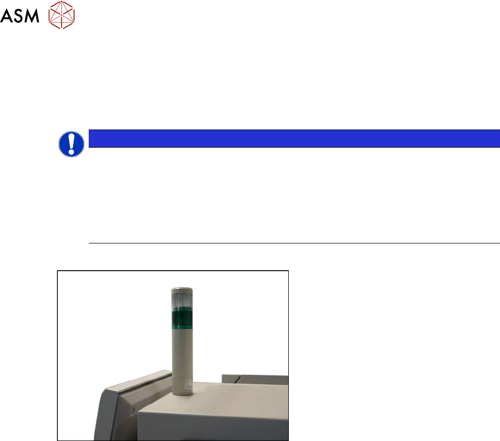
Overview
Fig.140: Indicator lamp (version1))
Two color indicator lamp (white/green)
Removal
► Switch off the machine, disconnect it from the power supply and secure it to prevent
unauthorized reactivation.
1.2 "Preparatory work..." [}16]
► Unplug the electrical connections to the indicator lamp. You might like to mark their positions
to make clear assignment easier later on.
► Remove the screw fastening the indicator lamp.
Installation
► Installation is performed by following the above instructions in the reverse order.
When inserting the illuminant, observe the identification on the casing.
► Check the function of the indicator lamp.

4 Electrics and control system
4.5 Indicator lamp
Service Manual SIPLACE X-Serie S 06/2019 117
4.5.1.2 Replacing the Light Elements in the Indicator Lamp
Parts, equipment and tools
●
Incandescent lamp BA15d 24V/5W [03005204-xx]
or
LED bulb socket B15d 24V AC/DC clear [03099236-xx]
Removal/installation
► Switch off the machine, disconnect it from the power supply and secure it to prevent
unauthorized reactivation.
1.2 "Preparatory work..." [}16]
You can individually lift off each color segment (= base unit) of the indicator lamp.
► Lift off the relevant color segment with a short rotation.
► Remove the light element and insert a new one.
When inserting the illuminant, observe the identification on the casing.
► Re-attach the yellow and the green color segment with a short rotation.
► Check the function of the indicator lamp.
4.5.1.3 Conversion 2-/3-Part Indicator Lamp
NOTICE
Exemplary description
The following section describes the conversion of a two-part lamp into a three-part lamp.
The conversion of a three-part lamp into a two-part lamp is identical.
Parts, equipment and tools
●
For converting a two-part lamp into a three-part one:
Light tower three colors [00519896Sxx]
●
For converting a three-part lamp into a two-part one:
Light tower two colors [00519895Sx]
Procedure
► Switch off the machine, disconnect it from the power supply and secure it to prevent
unauthorized reactivation.
1.2 "Preparatory work..." [}16]
You can individually lift off each color segment (= base unit) of the indicator lamp.
► Lift off the white color segment with a short rotation.
► Insert the new color segments and new light elements, if necessary.
When inserting the light element, take note of the designation on the casing.
► Attach the yellow and the green color segment with a short rotation.
► Set the relevant option (two/three color) in the machine configuration.
► Check the function of the indicator lamp.
4 Electrics and control system
4.5 Indicator lamp
118 Service Manual SIPLACE X-Serie S 06/2019
4.5.2 Indicator lamp (version2)
4.5.2.1 Replacing the indicator lamp/module
Parts
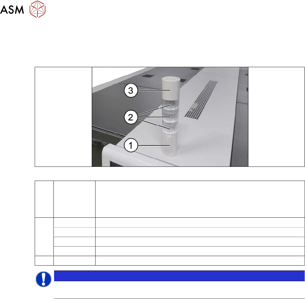
Fig.141: Indicator lamp
1 03148080‑xx Tower light standard series LR5
Consists of:
●
03162662-xx basic module
●
03103211-xx connection cable
2 03162664-xx LED module LR5-E-RZ 50mm red, transparent
03162665-xx LED module LR5-E-YZ 50mm yellow, transparent
03162663-xx LED module LR5-E-GZ 50mm green, transparent
03162666-xx LED module LR5-E-CZ 50mm white, transparent
3 03162667‑xx Buzzer module LR5-BW 50mm
NOTICE
Do not separate the LED and its housing
The LED and the transparent housing can not be separated from one another.