00197042-04_SM_X-Serie-S_Customer_EN.pdf - 第151页
6 Gantries 6.3 X and Y axis Service Manual SIPLACE X-Serie S 06/2019 151 Fig.187: Travel range for X and Y axes (X series shown as example) 1. Safety distance between the gantries during placement: minimum 4mm . Depend…
6 Gantries
6.3 X and Y axis
150 Service Manual SIPLACE X-Serie S 06/2019
6.3.3 Mechanical adjustment of the incremental encoder
The incremental encoders (read units) on the X and Y axis are adjusted exactly to the position of
the incremental scale. The two limit marks on the incremental encoder show where the top/bottom
positions of the scale should be.
Set the incremental encoder mechanically to a distance of 0.75 mm to the incremental encoder.
NOTICE
Plastic disks
To set this distance, use one or more small plastic disks with a total thickness of 0.75mm.
► Feeler gauge 0.75mm plastic [03090774-xx]
After this adjustment of the incremental encoder you have to check the zero pulse and track sig-
nals.
Correct installation should ensure correct count and zero pulse signals. For troubleshooting pur-
poses (error analysis and fixing), you will need to measures these signals.
Please also observe section 6.3.8 "Track Signals and Zero Pulse" [}153].
6.3.4 Travel Ranges and Speed Monitoring
The travel range of the X and Y axes will be determined during machine calibration.
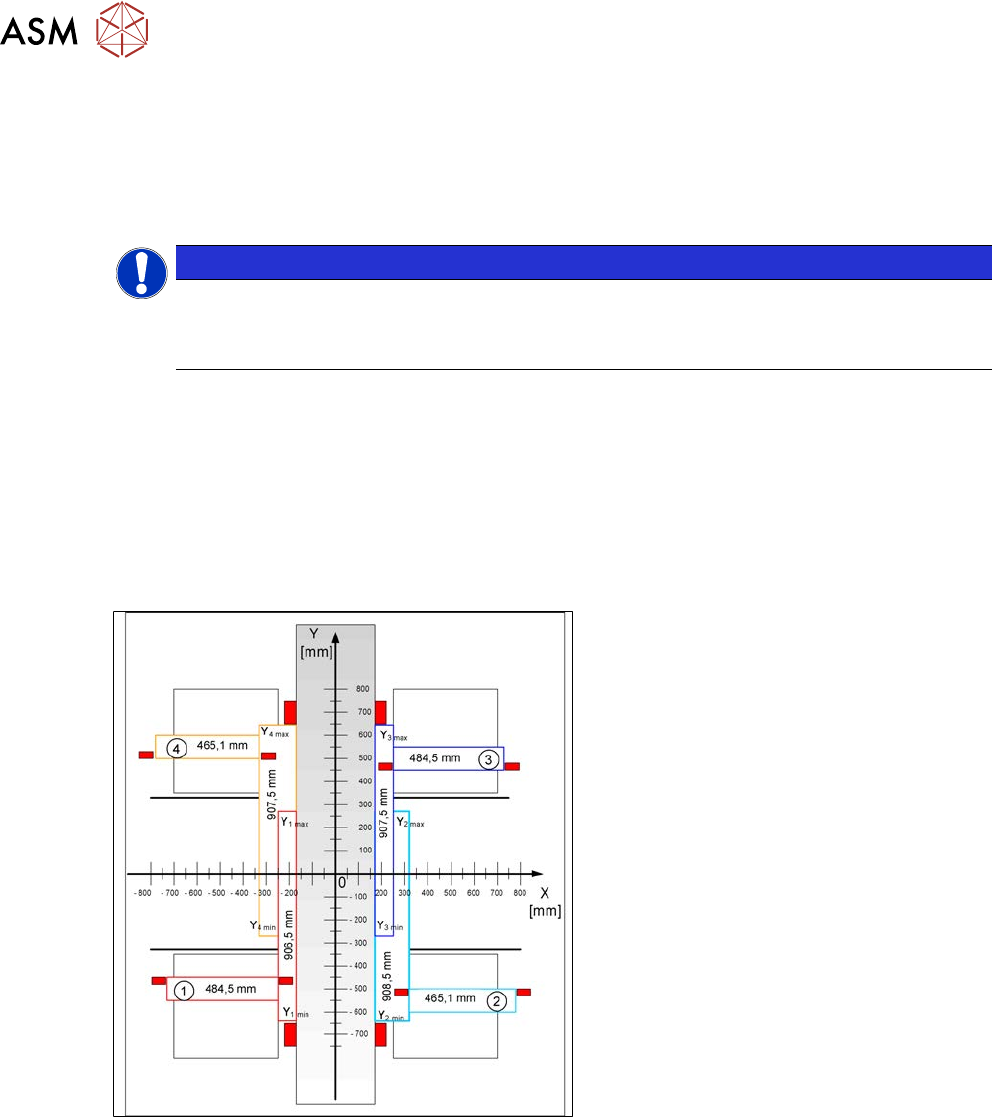
Fig.186: Travel range for X and Y axes (X series shown as
example)
1) to 4) = gantry 1 to 4
The end of the X axis travel range is + or -
0.5 mm before the software limit switch,
which is 1.5 mm before the buffer. A safety
distance of 2.0 mm to the buffer is adequate
if the X axis moves into this area with ex-
cessive speed.
The end of the Y axis travel range is + or -
2.0 mm before the software limit switch. The
Y axis travel range for a particular place-
ment area is monitored in one direction by
the software limit switch and a buffer. In the
other direction, there is a permanent ex-
change of communication between the axes
and their positions, via the SPI bus. (see
also 6.3.7 "Anticrash Function" [}152]).
6 Gantries
6.3 X and Y axis
Service Manual SIPLACE X-Serie S 06/2019 151
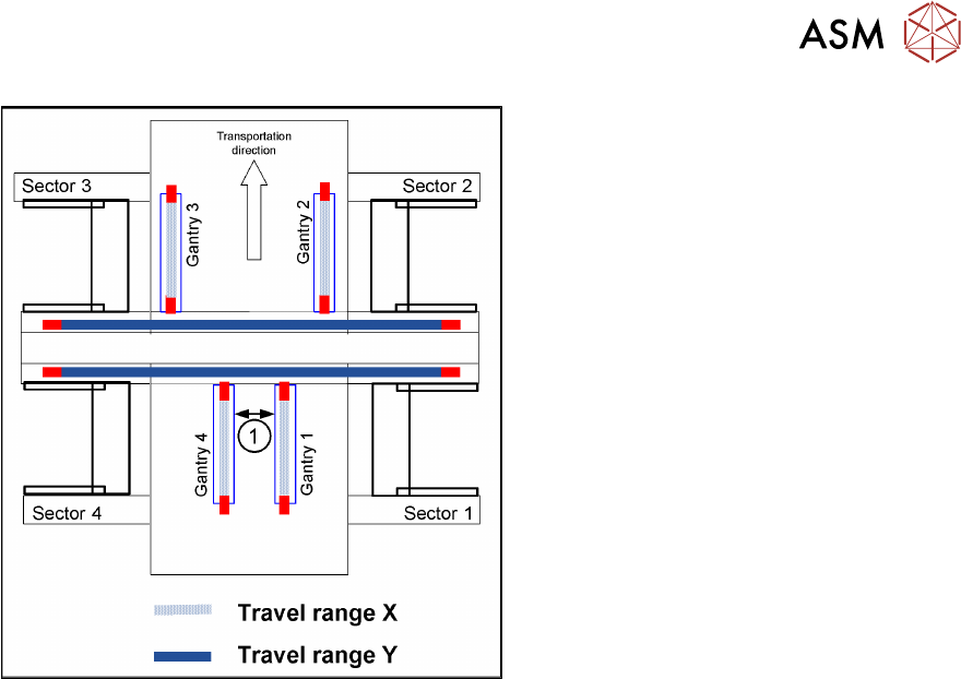
Fig.187: Travel range for X and Y axes (X series shown as
example)
1. Safety distance between the gantries
during placement: minimum 4mm.
Depending on the placement mode (I-place-
ment or alternating), the gantries will operate
in one placement area fully independently.
This means that one gantry does not need
to know the position of the other one.
6.3.5 Error "Gantry Crash"
A “gantry crash” error is established by calculating the position difference and speed difference for
both axes. A gantry crash error is signaled via the (M) GCUs and the CAN Bus. After the "gantry
crash" error message has been issued, both gantries need to be referenced.
6.3.6 Count Error
If the (M)GCU detects a "fatal count error", the axis concerned will be released and the anticrash
function disabled. The other axis is informed of this in the status information and will also disable
the anticrash function. The released axis now needs to be referenced again.
After this, the anticrash function will be re-enabled for both axes.
6 Gantries
6.3 X and Y axis
152 Service Manual SIPLACE X-Serie S 06/2019
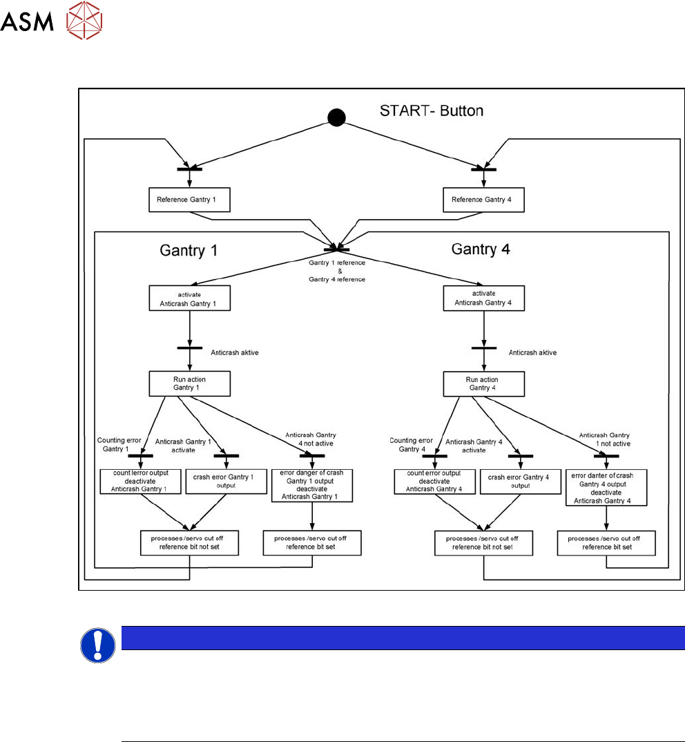
6.3.7 Anticrash Function
Fig.188: Example of the anticrash function sequence in placement area 1
NOTICE
(M)GCU, (M)HCU
The (M)GCU and the (M)HCU consist of a control module (axis card) and a power module
(servo).
The (M)GCU and (M)HCU combine control and performance sections. There is no longer a
separation between the axis and servo cards.