00197042-04_SM_X-Serie-S_Customer_EN.pdf - 第153页
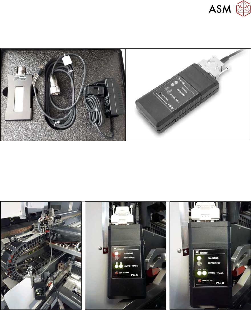
6 Gantries 6.3 X and Y axis Service Manual SIPLACE X-Serie S 06/2019 153 6.3.8 Track Signals and Zero Pulse Equipment and tools Fig.189: Test devices PG1-I and PG-U ● For MS22/25 incremental encoder: test device PG1-I […
6 Gantries
6.3 X and Y axis
152 Service Manual SIPLACE X-Serie S 06/2019
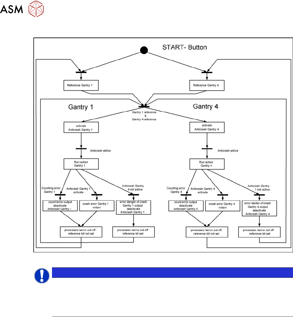
6.3.7 Anticrash Function
Fig.188: Example of the anticrash function sequence in placement area 1
NOTICE
(M)GCU, (M)HCU
The (M)GCU and the (M)HCU consist of a control module (axis card) and a power module
(servo).
The (M)GCU and (M)HCU combine control and performance sections. There is no longer a
separation between the axis and servo cards.
6 Gantries
6.3 X and Y axis
Service Manual SIPLACE X-Serie S 06/2019 153
6.3.8 Track Signals and Zero Pulse
Equipment and tools
Fig.189: Test devices PG1-I and PG-U
●
For MS22/25 incremental encoder: test device PG1-I [03102699‑xx]
●
For MS20/30/35 incremental encoder: test device PG-U [03071361‑xx]
Checks
Proceed as follows to check the zero pulse:
► Switch off the machine.
Fig.190: Test device (example of test device PG-U on a SIPLACE SX1 shown)
► Unplug the incremental encoder from the head interface or the gantry interface and connect it
to the test device (see also 6.3.8.1 "Test device – operation" [}154]).
► Move the head or gantry manually back and forth. This movement enables you to read the
correct track signal progress from the test device.
► If the track signal is not within the tolerance range, you will need to reset the incremental en-
coder. The incremental encoder has then been fitted either too near, too far away, inclined
and/or displaced.
6 Gantries
6.3 X and Y axis
154 Service Manual SIPLACE X-Serie S 06/2019
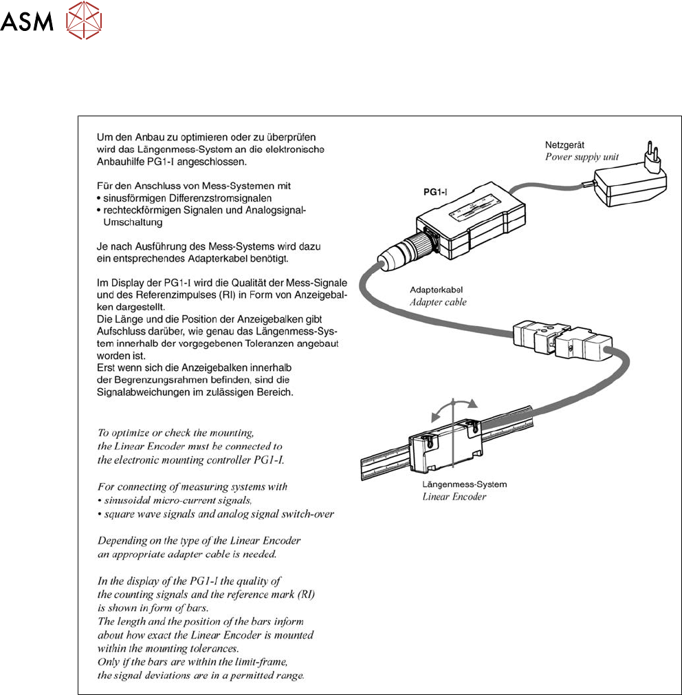
6.3.8.1 Test device – operation
Test device PG1-I [03102699‑xx]
Fig.191: Operation of test device PG1-I - 1