00197042-04_SM_X-Serie-S_Customer_EN.pdf - 第17页
1 Introduction 1.2 Preparatory work... Service Manual SIPLACE X-Serie S 06/2019 17 ► Lock out the machine. ð Attach a lock wherever possible. Fig.3: Attaching a padlock to the main power switch Secure main switch ► Secu…
1 Introduction
1.2 Preparatory work...
16 Service Manual SIPLACE X-Serie S 06/2019
1.1.9 Classification of the optical systems
1.1.9.1 Classification of the whole machine
Fig.2: Laser class 2
The ready-to-operate overall machine is assigned
to laser class°2.
The laser classes are determined according to
DIN EN 60825-1:2014.
1.1.9.2 Laser classification
The following modules are assigned to laser class 2:
●
Component sensor on the SpeedStar
●
Component sensor on the MultiStar
●
Laser light barriers at the board conveyor
1.1.9.3 Classification of the camera systems
WARNING
LEDs
The camera illumination systems are fitted with light LEDs. These are assigned to risk
group 1 according to IEC 62741:2006.
► Do not look into beam!
1.2 Preparatory work...
Purpose and scope
Before performing any preventive maintenance work, conversion work or service work, a procedure
of locking and tagging must be followed and warning signs must be attached if not stated other-
wise. If you do not need to switch off the machine, this will be clearly stated.
The procedure, when followed correctly, eliminates the possibility of an employee being injured.
NOTICE
Additional safety measures
This procedure represents the minimum lock out and tag out requirements for the machine
during preventive maintenance work and service work. Any additional safeguards needed
to complete work safely can be specified by facilities supervision, the safety officer, the
safety committee and the health department.
Description
Whenever it becomes necessary to isolate, control and release energy, the following procedure is
to be followed.
► Notify all affected employees.
► Switch off the machine and all additional devices. Carry out all normal stopping procedures:
ð Press the STOP button.
ð Shut down the station computer.
ð Switch off the machine using the main switch.
► Isolate the machine from all its energy sources:
ð Shut off the compressed air supply.
ð Shut off the main power supply.
1 Introduction
1.2 Preparatory work...
Service Manual SIPLACE X-Serie S 06/2019 17
► Lock out the machine.
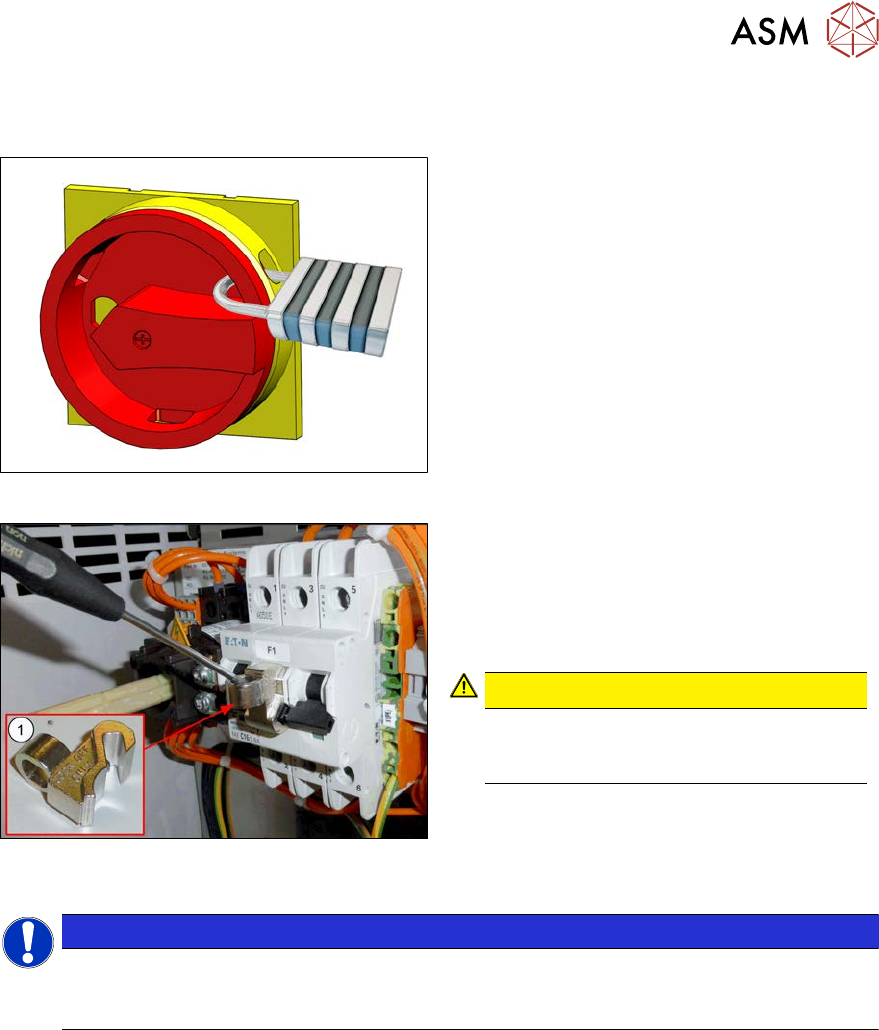
ð Attach a lock wherever possible.
Fig.3: Attaching a padlock to the main power switch
Secure main switch
► Secure the main switch with a padlock.
Fig.4: Attaching the lockout attachment Z-IS/SPE-1TE
[03123101-xx]
Secure circuit breaker
The lockout attachment can prevent the
machine from being switched on inadvertently.
► Switch off the machine.
► Set the circuit breaker to OFF.
CAUTION!
The lockout attachment may only be at-
tached when the machine is switched
off!
.
► Attach the lockout attachment(1) to the
circuit breaker.
► Secure the circuit breaker with a padlock.
NOTICE
Lockout attachment in the service box of your machine
On machines that are delivered from June 2016, the lockout attachment [03123101‑xx] is
located in the service box.
1 Introduction
1.2 Preparatory work...
18 Service Manual SIPLACE X-Serie S 06/2019
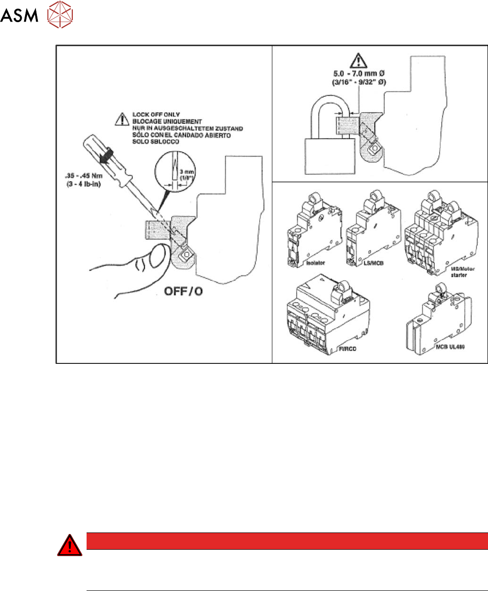
Fig.5: Lockout attachment Z-IS/SPE-1TE [03123101-xx]
► Alternatively, you can attach warning signs:
Any machine that can be locked must be locked.
However, there are situations where energy isolating devices cannot accommodate locks. In
these cases, the energy isolating devices must be tagged appropriately to warn employees
that the machine is currently de-energized for service purposes. The tag or label must be
fastened securely in a position visible from all sides and it may only be removed by the person
who attached it.
► Release of stored energy:
Energy stored as compressed air in the compressed air supply or electrical energy stored in
electrolytic capacitors must be released by appropriate means.
After switching off the machine, wait until the voltages have discharged and the compressed
air has released, so that work can be performed without any risk.
DANGER
Checking for absence of voltage!
► Before you start working, check the power supply for absence of voltage and observe
the waiting times!
► Testing the lock out:
The lock can be easily tested by pressing the START button.