00197042-04_SM_X-Serie-S_Customer_EN.pdf - 第171页
6 Gantries 6.4 Trailing cable and printed circuit boards Service Manual SIPLACE X-Serie S 06/2019 171 Fig.217: Gantry interface [03089221-03] Gantry interface [03089221-03]: This gantry interface is used at gantries 2 a…
6 Gantries
6.4 Trailing cable and printed circuit boards
170 Service Manual SIPLACE X-Serie S 06/2019
6.4.4 Replacing the gantry interface
Parts, equipment and tools
●
Gantry interface gantry 1 and 3 SX4a [03089220-xx]
●
Gantry interface gantry 2 and 4 SX4a [03089221-xx]
NOTICE
Machines from Serial Number Hxxxx
The gantry interface version used for machines from serial number Hxxxx must be at least -03.
Overview
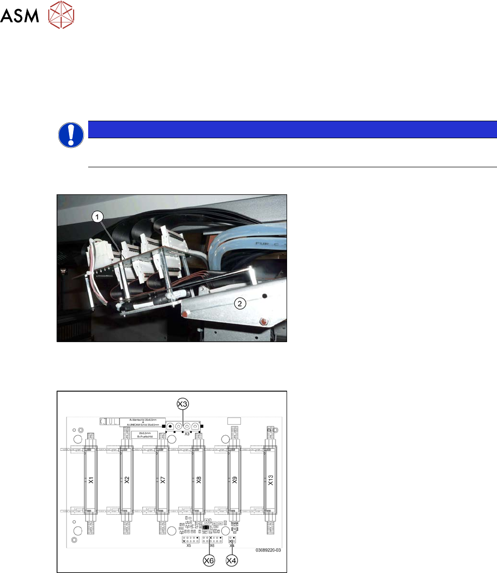
Fig.215: Gantry interface
1. Gantry interface
2. Trailing cable holder on gantry
Overview
Fig.216: Gantry interface [03089220-03]
Gantry interface [03089220-03]:
This gantry interface is used at gantries 1
and 3.
X3) Y axis motor power
X4) Y axis motor temperature sensor
X6) Y axis incremental encoder
6 Gantries
6.4 Trailing cable and printed circuit boards
Service Manual SIPLACE X-Serie S 06/2019 171
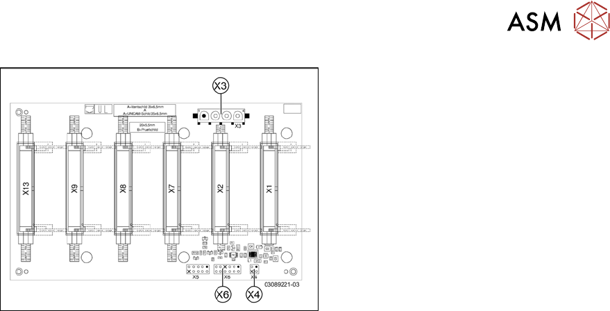
Fig.217: Gantry interface [03089221-03]
Gantry interface [03089221-03]:
This gantry interface is used at gantries 2
and 4.
X3) Y axis motor power
X4) Y axis motor temperature sensor
X6) Y axis incremental encoder
Removal
► Switch off the machine, disconnect it from the power supply and secure it to prevent
unauthorized reactivation.
1.2 "Preparatory work..." [}16]
► Unplug all electrical connections to the gantry interface. You may want to mark the positions
of these connections to make clear assignment easier later on.
► Remove the screws fastening the gantry interface and remove the gantry interface from the
machine.
Installation
► Follow the removal instructions in reverse order for installation.
6 Gantries
6.4 Trailing cable and printed circuit boards
172 Service Manual SIPLACE X-Serie S 06/2019
6.4.5 Replacing the Head Interface
Parts, equipment and tools
NOTICE
SIPLACE C&P20 P
If converting to a SIPLACE C&P20 P, you must fulfil the following requirements:
► The head interface must have at least FS03.
► The power cube [03055514-xx] must have at least FS02. Head interfaces from FS03
fulfil this requirement.
●
Select the appropriate head interface:
Machine type Gantry Head interface
SIPLACE X3 S, X4 S (micron) All Module head interface C700X-L HR
[03091013‑xx]
SIPLACE X4i S (micron) 1 and 3
SIPLACE X4i S (micron) 2 and 4 (rotated) Module head interface C700X-R HR
[03091023‑xx]
●
If required, cover plate head board assembly [03108367-xx] or
cover plate head board rotated assembly [03108392-xx]
●
If needed, 2x dummy plugs (plastic covers) [00368931-xx]
●
Loctite 241 or 243
Overview
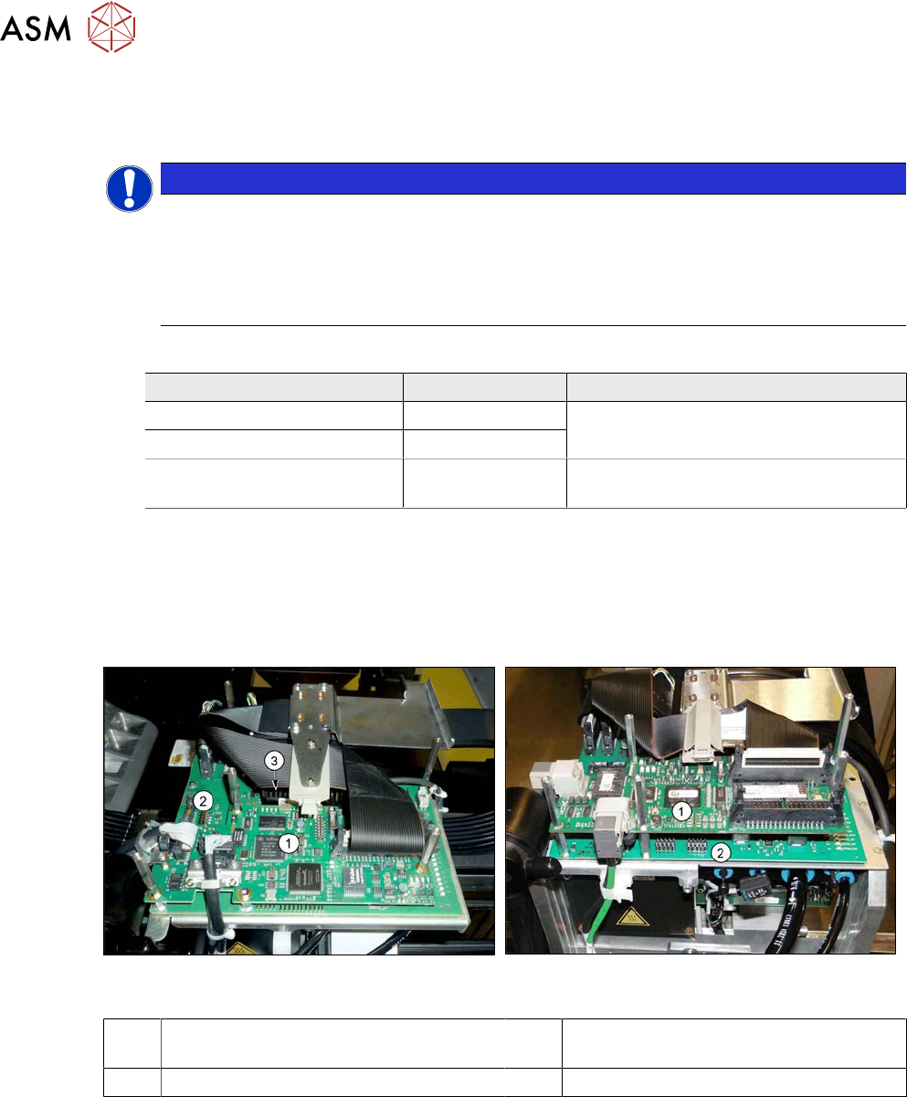
Fig.218: Boards on the gantry (up to Gxxxx, without
GigE)
Fig.219: Boards on the gantry (from Hxxxx, with GigE)
1 Vision board spread spectrum / Vision
Head Interface (VHI)
2 Head interface
3 Power cube on the head interface
Removal
► Switch off the machine, disconnect it from the power supply and secure it to prevent
unauthorized reactivation.
1.2 "Preparatory work..." [}16]