00197042-04_SM_X-Serie-S_Customer_EN.pdf - 第174页
6 Gantries 6.4 Trailing cable and printed circuit boards 174 Service Manual SIPLACE X-Serie S 06/2019 6.4.5.1 Head interface C700X-L/R HR There are two head interface designs. Depending on the gantry, either head interfa…
6 Gantries
6.4 Trailing cable and printed circuit boards
Service Manual SIPLACE X-Serie S 06/2019 173
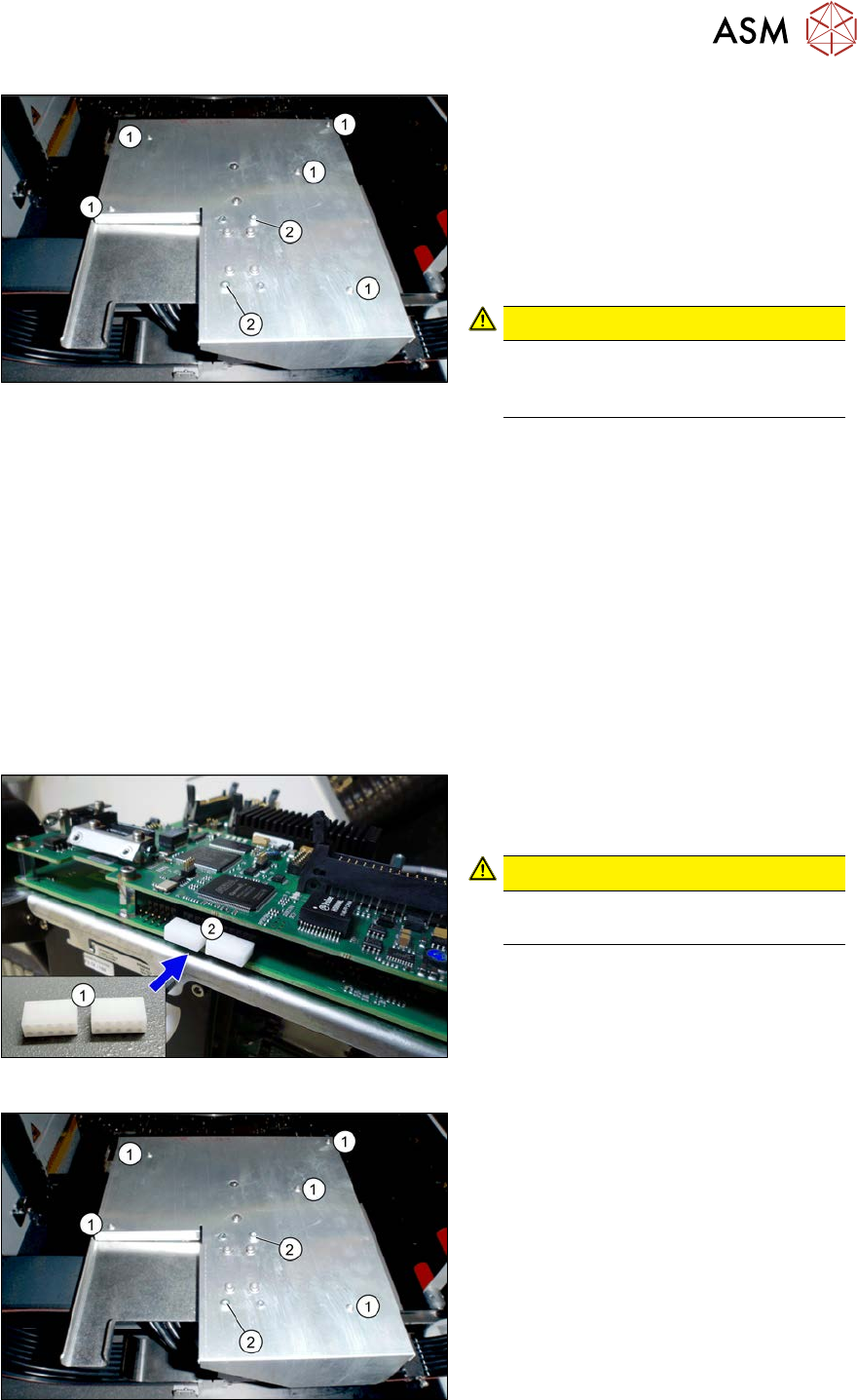
Fig.220: Board cover
1. Fastening screws 5x
2. If present:
fastening screws 2x (with Loctite)
► Remove the fastening screws(1).
► If present: remove the fastening
screws(2).
► Remove the board cover.
CAUTION!
To avoid short circuits, only dismantle
the cover when the machine is
switched off!
.
► Dismantle the Vision board spread spectrum. For more information, read section 6.4.7 "Repla-
cing the Vision board spread spectrum HCU" [}178].
► Unplug all connector from the head interface and remove all cable ties. You might like to mark
their positions to make clear assignment or replacement easier later on.
► Remove the screws fastening the head interface.
► Carefully remove the head interface. Make sure that the connectors to the head adapter HCU
are not damaged.
Installation
► Apply the DIP switch setting from the old head interface.
See also:6.4.5.1 "Head interface C700X-L/R HR" [}174]
► Follow the removal instructions in reverse order for further installation. Also observe the fol-
lowing instructions:
Fig.221: Dummy plug
► Secure the connector X1(2) on the
head interface, if present, with two
dummy plugs(1).
CAUTION!
Without the dummy plugs, there is a
risk of short circuit at the board cover!
.
Fig.222: Board cover
1. Fastening screws 5x
2. Fastening screws 2x (withLoctite)
► Secure the two screws(2) on the board
cover with Loctite 241 or 243.
6 Gantries
6.4 Trailing cable and printed circuit boards
174 Service Manual SIPLACE X-Serie S 06/2019
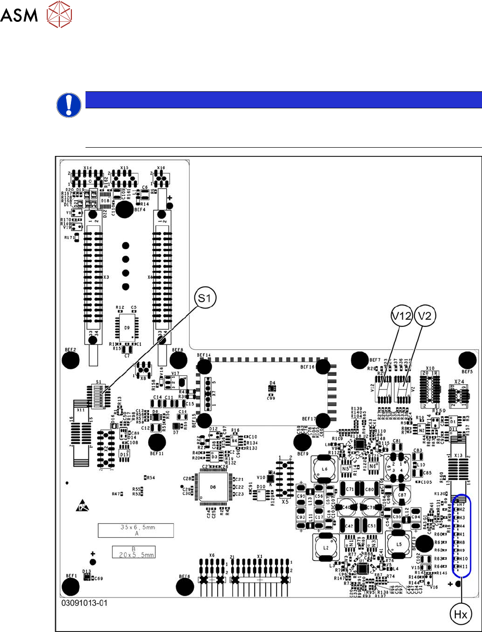
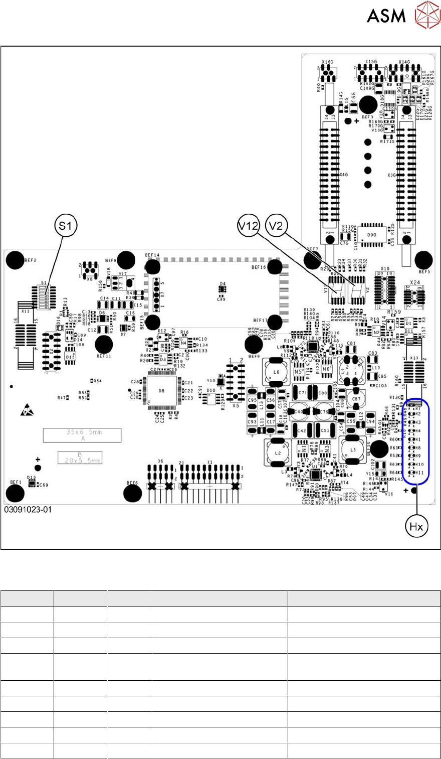
6.4.5.1 Head interface C700X-L/R HR
There are two head interface designs. Depending on the gantry, either head interface C700X-L or
C700X-R will be used.
NOTICE
C&P20 P
If you are converting to a C&P20 P, you must have function state -03 or higher for the head
interface.
Fig.223: Standard gantry (not rotated) [03091013-01]
6 Gantries
6.4 Trailing cable and printed circuit boards
Service Manual SIPLACE X-Serie S 06/2019 175
Fig.224: Rotated gantry (gantry 2 and 4 at X4i S) [03091023-01]
LEDs (Hx) [03091013-01] [03091023-01]
LED Color Status Signal name Description
H1 RD - HCU1_LED_ERROR Not used
H2 RD ON POWERFAIL_BASE PowerFail from power supply
H3 RD ON EMERGENCY-STOP_3V Emergency stop: cover opened
H4 RD ON POWERFAIL_LOCAL_3V PowerFail local: errors at 1.5V,
3.3V, 5V, +15V, -15V
H7 RD ON X_TEMP_SENS X motor: temperature too high
H8 RD - HCU2_LED_ERROR Not used
H9 RD - HCU1_LED_READY Not used
H10 RD - HCU2_LED_READY Not used
H11 GN ON LED_5V_OK FPGA OK