00197042-04_SM_X-Serie-S_Customer_EN.pdf - 第176页
6 Gantries 6.4 Trailing cable and printed circuit boards 176 Service Manual SIPLACE X-Serie S 06/2019 7-segment display V2 [03091013-01] [03091023-01] Display Status Description Decimal point Flashes HCU2 OK 7-segment di…
6 Gantries
6.4 Trailing cable and printed circuit boards
Service Manual SIPLACE X-Serie S 06/2019 175
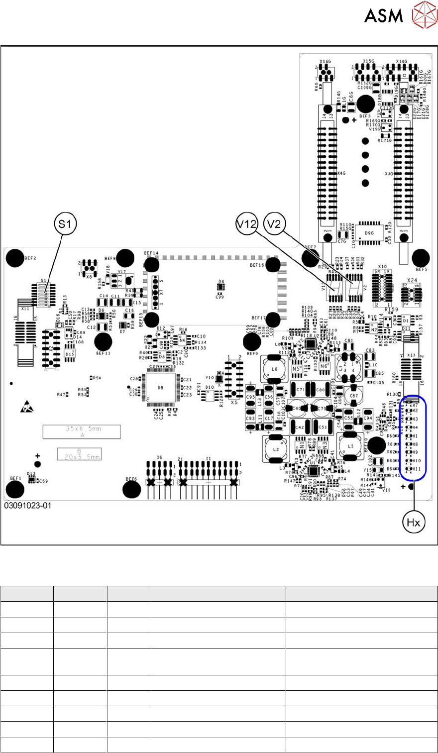
Fig.224: Rotated gantry (gantry 2 and 4 at X4i S) [03091023-01]
LEDs (Hx) [03091013-01] [03091023-01]
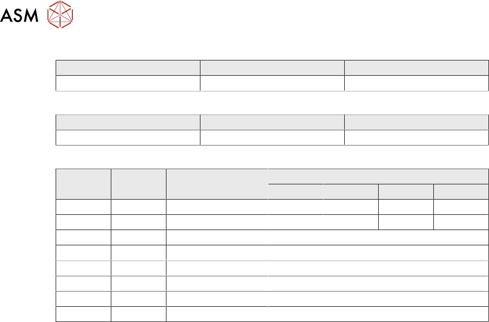
LED Color Status Signal name Description
H1 RD - HCU1_LED_ERROR Not used
H2 RD ON POWERFAIL_BASE PowerFail from power supply
H3 RD ON EMERGENCY-STOP_3V Emergency stop: cover opened
H4 RD ON POWERFAIL_LOCAL_3V PowerFail local: errors at 1.5V,
3.3V, 5V, +15V, -15V
H7 RD ON X_TEMP_SENS X motor: temperature too high
H8 RD - HCU2_LED_ERROR Not used
H9 RD - HCU1_LED_READY Not used
H10 RD - HCU2_LED_READY Not used
H11 GN ON LED_5V_OK FPGA OK
6 Gantries
6.4 Trailing cable and printed circuit boards
176 Service Manual SIPLACE X-Serie S 06/2019
7-segment display V2 [03091013-01] [03091023-01]
Display Status Description
Decimal point Flashes HCU2 OK
7-segment display V12 [03091013-01] [03091023-01]
Display Status Description
Decimal point Flashes HCU1 OK
DIP switch S1 [03091013-01] [03091023-01]
Switch Status Signal name Description
Gantry 1 Gantry 2 Gantry 3 Gantry 4
S1.1 OFF/ON Gantry_ID0 OFF ON OFF ON
S1.2 OFF/ON Gantry_ID1 OFF OFF ON ON
S1.3 OFF COM_BOOT_HCU ON: set HCU to bootstrap mode
S1.4 OFF RESET_HCU2 ON: Reset HCU2
S1.5 OFF RESET_HCU1 ON: Reset HCU1
S1.6 OFF FAN Not used
S1.7 OFF DCDC_OFF ON: Reset, when not all the voltages are present
S1.8 OFF HCU_1_2 Not used
6 Gantries
6.4 Trailing cable and printed circuit boards
Service Manual SIPLACE X-Serie S 06/2019 177
6.4.6 Replacing the Power Cube Module on the Head Interface
NOTICE
SIPLACE C&P20 P
The following additional conditions must be fulfilled for operating a SIPLACE C&P20P:
► The module power cube must have at least function state [03055514-02].
► You find a complete list of the prerequisites in section 8.5 "Replacing the SIPLACE
C&P20P/M2" [}313].
Overview
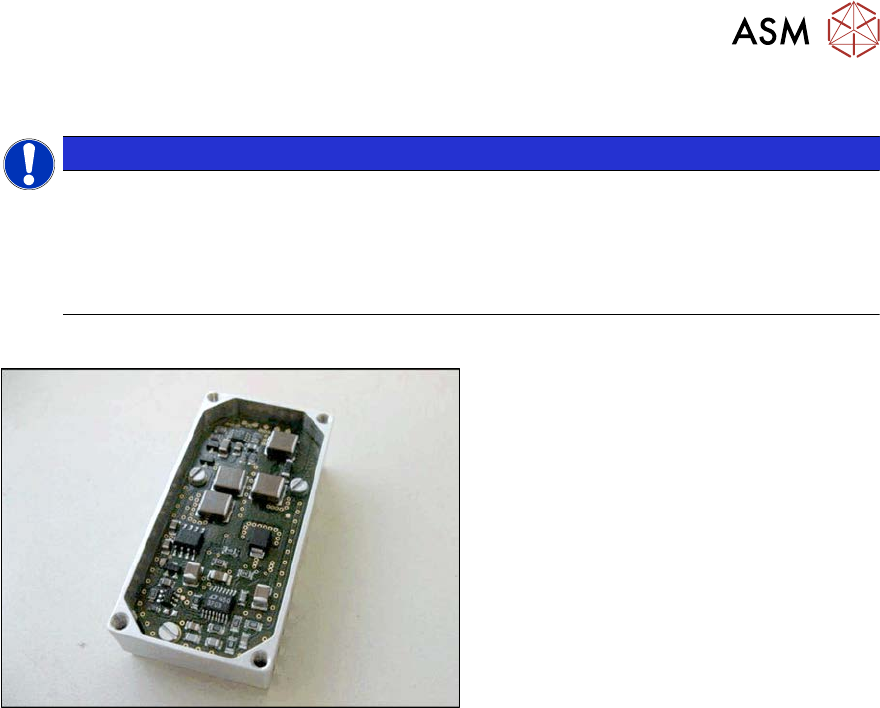
Fig.225: Powercube module
Powercube module [03055514-xx]
Removal
► Switch off the machine, disconnect it from the power supply and secure it to prevent
unauthorized reactivation.
1.2 "Preparatory work..." [}16]
► Dismantle the head interface. Also read section 6.4.5 "Replacing the Head Interface" [}172].
► Remove the four screws fastening the power cube and carefully lift off the power cube from
the head interface.
Installation
► Installation is performed by following the above instructions in the reverse order. Also observe
the following instructions:
– Make sure that the power cube is positioned correctly.