00197042-04_SM_X-Serie-S_Customer_EN.pdf - 第178页
6 Gantries 6.4 Trailing cable and printed circuit boards 178 Service Manual SIPLACE X-Serie S 06/2019 6.4.7 Replacing the Vision board spread spectrum HCU This section applies for SIPLACE X-Series S machines up to Gxxxx.…
6 Gantries
6.4 Trailing cable and printed circuit boards
Service Manual SIPLACE X-Serie S 06/2019 177
6.4.6 Replacing the Power Cube Module on the Head Interface
NOTICE
SIPLACE C&P20 P
The following additional conditions must be fulfilled for operating a SIPLACE C&P20P:
► The module power cube must have at least function state [03055514-02].
► You find a complete list of the prerequisites in section 8.5 "Replacing the SIPLACE
C&P20P/M2" [}313].
Overview
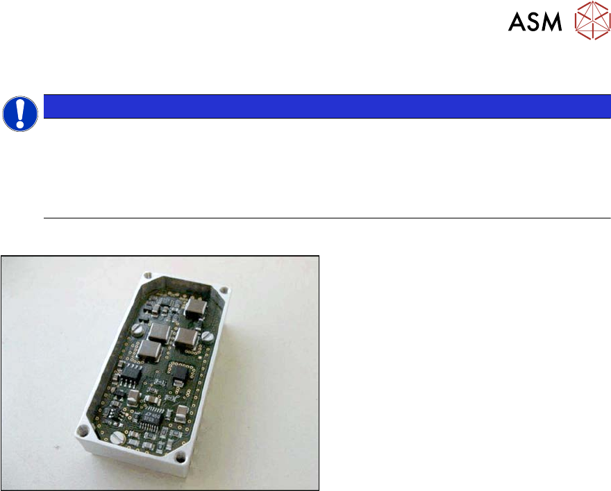
Fig.225: Powercube module
Powercube module [03055514-xx]
Removal
► Switch off the machine, disconnect it from the power supply and secure it to prevent
unauthorized reactivation.
1.2 "Preparatory work..." [}16]
► Dismantle the head interface. Also read section 6.4.5 "Replacing the Head Interface" [}172].
► Remove the four screws fastening the power cube and carefully lift off the power cube from
the head interface.
Installation
► Installation is performed by following the above instructions in the reverse order. Also observe
the following instructions:
– Make sure that the power cube is positioned correctly.
6 Gantries
6.4 Trailing cable and printed circuit boards
178 Service Manual SIPLACE X-Serie S 06/2019
6.4.7 Replacing the Vision board spread spectrum HCU
This section applies for SIPLACE X-Series S machines up to Gxxxx.
Parts, equipment and tools
●
Vision board spread spectrum HCU assembly [03067289-xx]
Overview
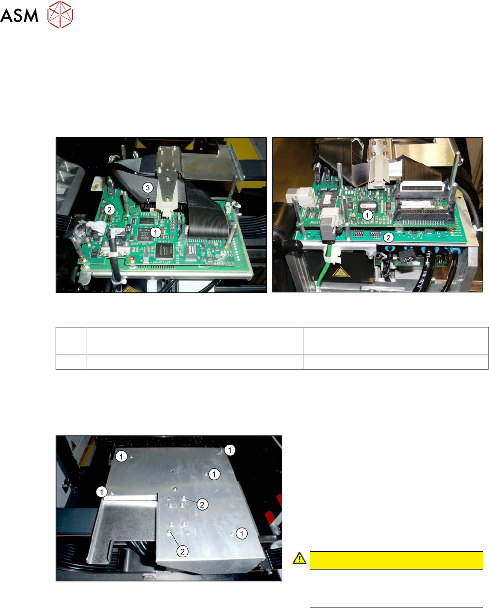
Fig.226: Boards on the gantry (up to Gxxxx, without
GigE)
Fig.227: Boards on the gantry (from Hxxxx, with GigE)
1 Vision board spread spectrum / Vision
Head Interface (VHI)
2 Head interface
3 Power cube on the head interface
Removal
► Switch off the machine, disconnect it from the power supply and secure it to prevent
unauthorized reactivation.
1.2 "Preparatory work..." [}16]
Fig.228: Board cover
1. Fastening screws 5x
2. If present:
fastening screws 2x (with Loctite)
► Remove the fastening screws(1).
► If present: remove the fastening
screws(2).
► Remove the board cover.
CAUTION!
To avoid short circuits, only dismantle
the cover when the machine is
switched off!
.
► Unplug all electrical connections to the Vision board spread spectrum. You may want to mark
the positions of these connections to make clear assignment easier later on.
► Remove thescrews fastening the Vision board spread spectrum and remove the board.
6 Gantries
6.4 Trailing cable and printed circuit boards
Service Manual SIPLACE X-Serie S 06/2019 179
Installation
► Follow the removal instructions in reverse order for installation. Also observe the following
instructions:
– If there is no clamp for the PCB camera cable on the new board, take this off the old board
and fit it on the new one.
– Set the correct gantry ID. Take the setting from the dismantled board (see also 6.4.8 "Vis-
ion board spread spectrum" [}180]).
– Before fitting the board cover, check whether the plastic covers are present on connector
X1 (see below).
– Two screws on the board cover need to be secured with Loctite 241 or 243 (see above).
– Then perform a firmware update (see 6.9 "eSW Download (SW 70x)" [}202]).
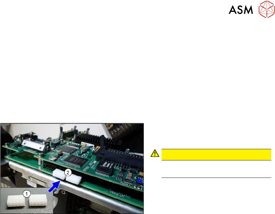
Fig.229: Dummy plug
► Secure the connector X1(2) on the
head interface, if present, with two
dummy plugs(1).
CAUTION!
Without the dummy plugs, there is a
risk of short circuit at the board cover!
.