00197042-04_SM_X-Serie-S_Customer_EN.pdf - 第181页
6 Gantries 6.4 Trailing cable and printed circuit boards Service Manual SIPLACE X-Serie S 06/2019 181 6.4.9 Replacing the Vision head interface (VHI) This section applies for SIPLACE X-Series S machines from Hxxxx. Parts…
6 Gantries
6.4 Trailing cable and printed circuit boards
180 Service Manual SIPLACE X-Serie S 06/2019
6.4.8 Vision board spread spectrum
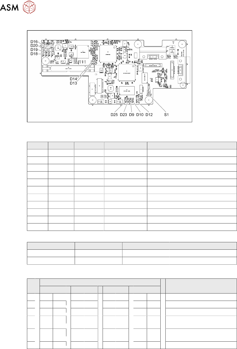
Fig.230: 03067289-02
LED [03067289-02]
LED Color Status Signal name Description
D9 GN ON LED_XC_OK RUN
D10 RD ON LED_XC_ERR ERROR
D12 RD ON XC_RESET RESET
D13 GN ON IO/LVDS51P PCB camera active
D14 GN ON IO/LVDS51N CO camera active
D16 GN ON P12VCAM_I +12VDC for camera
D18 GN ON P5VCAM +5VDC for camera
D19 GN ON P2.5VCAM + 2.5 VDC for camera
D20 GN ON P3.3VCAM + 3.3VDC for camera
D23 GN ON P5V +5VDC
D25 GN ON P15V +15VDC
Dip switch S1 [03067289-02]
Switch Status Signal name Description
S1.1 OFF HW_RESET ON: RESET CAN controller
S1.2 OFF CAN_ID Not used
6.4.8.1 DIP Switch on the Vision Board (Digital Version 02)
S Gantry* Comments
1 2 3 4
1 OFF OFF OFF OFF Reset - CAN processor
2 OFF ON OFF ON PID0 address switch 1 -> gantry
3 OFF OFF ON ON PID1 address switch 2 -> gantry
4 OFF OFF OFF OFF CAN R - switch for the terminal
resistor on the CAN bus
5 ON ON ON ON Speed: ON = 1Mbit/s, OFF =
500Kbit/s
6 ON ON ON ON CAN ID - for X machine ON
* Not all gantries may be available, depending on the machine type.
6 Gantries
6.4 Trailing cable and printed circuit boards
Service Manual SIPLACE X-Serie S 06/2019 181
6.4.9 Replacing the Vision head interface (VHI)
This section applies for SIPLACE X-Series S machines from Hxxxx.
Parts, equipment and tools
●
Vision Head Interface (VHI) [03115454-xx]
If required:
●
Cover plate head board assembly [03108367-xx] or
cover plate head board rotated assembly [03108392-xx]
Overview
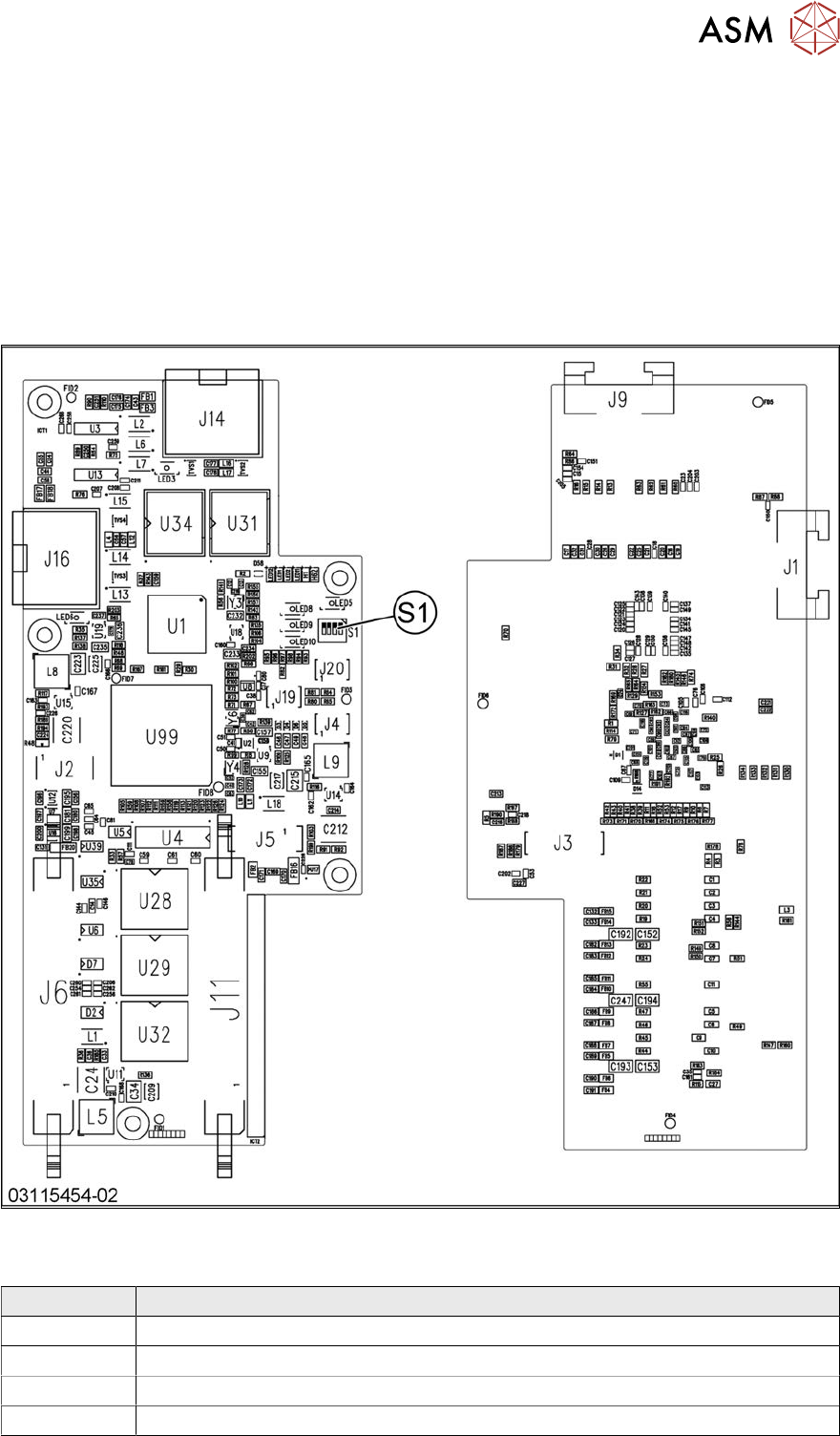
Fig.231: Vision head interface
Press-fit connections
Connector Description
J14 CAM1 – PCB camera
J16 CAM2 – component camera
J6, J11 Trailing cable
J5 Power supply
6 Gantries
6.4 Trailing cable and printed circuit boards
182 Service Manual SIPLACE X-Serie S 06/2019
DIP switch S1
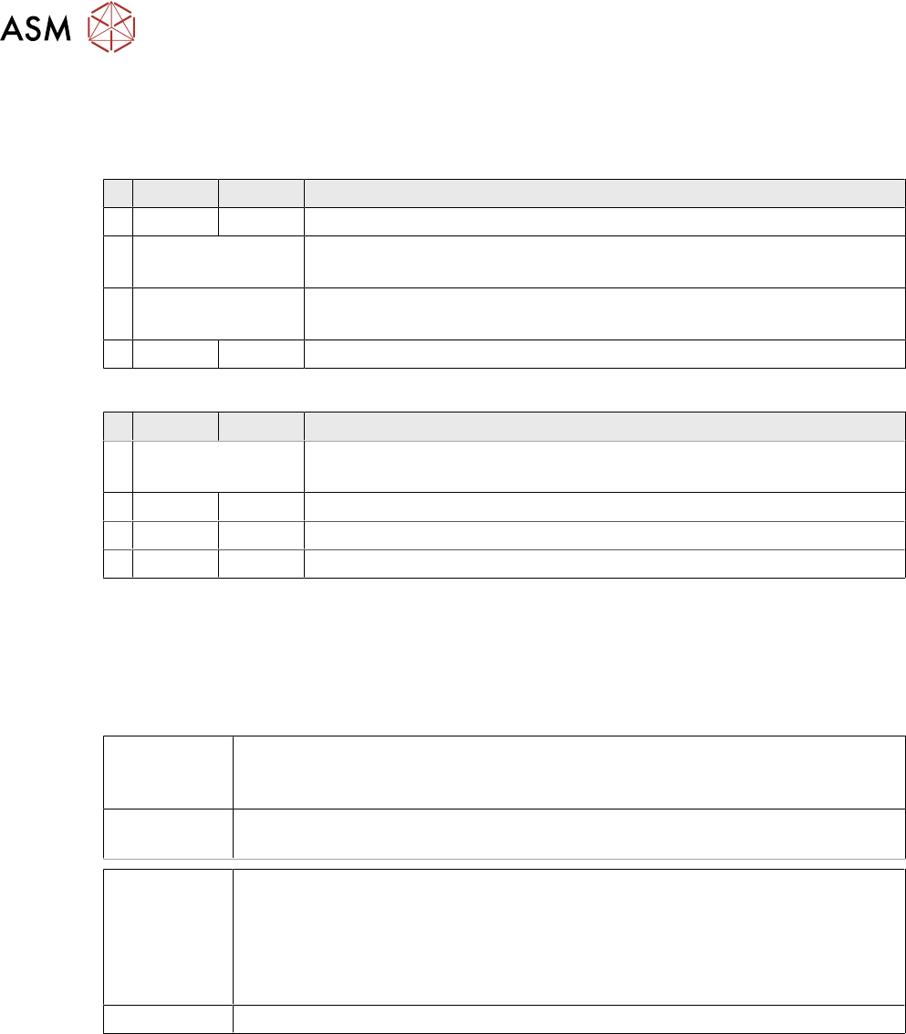
The DIP S1 switch settings depend on the board version:
DIP switch S1 [03115454-01]
ON OFF Comments
1 ON Spread OFF/ON
2 See text X-Series S: ON
All other machines: OFF
3 See text X-Series S: OFF
All other machines: ON
4 OFF CAN-R ON/OFF
DIP switch S1 [03115454-02 und -03]
ON OFF Comments
1 See text X-Series S: OFF
All other machines: ON
2 OFF Reserved
3 ON EEPROM
4 OFF CAN-R ON/OFF
Removal/installation
► Removal and installation of the VHI is the same as that for the Vision board spread spectrum.
Please read section 6.4.7 "Replacing the Vision board spread spectrum HCU" [}178]. Pay at-
tention to the DIP switch S1.
Troubleshooting
Errors: Image transmission errors occur at cameras of type GigE.
Potential error message:
FM 33332: image transmission to SIPLACE Vision computer interrupted.
Solution: ► Check the DIP switches for the VHI. Pay attention to the function state of the
board.
Errors: When starting the station software, cameras of type GigE are sometimes not re-
cognized.
Potential error messages:
FM 33378: unable to address camera (242).
FM 33209: unable to initialize camera with specified sensor ID.
FM 31904: unable to initialize machine hardware.
Solution: ► Contact the SIPLACE Service team for details.