00197042-04_SM_X-Serie-S_Customer_EN.pdf - 第185页
6 Gantries 6.5 GCU and MGCU Service Manual SIPLACE X-Serie S 06/2019 185 6.5.3 Overview of GCUs Fig.234: Overview of GCUs
6 Gantries
6.5 GCU and MGCU
184 Service Manual SIPLACE X-Serie S 06/2019
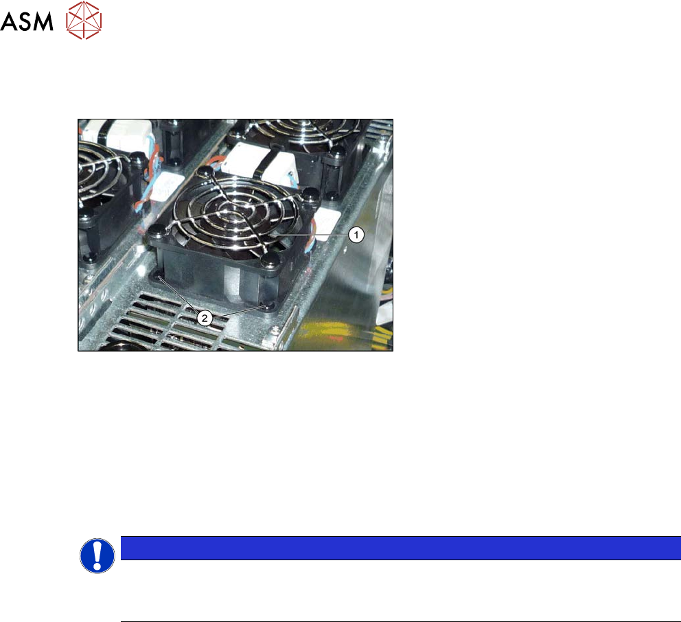
6.5.2 Replacing the GCU fan
Parts, equipment and tools
Fig.233: Overview – fan on the GCU
1. GCU fan [03060954-xx]
2. Plastic expansion rivets
(snap rivet DRM 4x4.5-5.5 sw
SR-4070B [03106012-xx])
These are supplied with the fan.
Removal
► Switch off the machine, disconnect it from the power supply and secure it to prevent
unauthorized reactivation.
1.2 "Preparatory work..." [}16]
► Unplug the cable from the fan. You may want to mark the position, to make clear assignment
easier later on.
► Pull out the four expansion rivets on the fan and then remove the fan.
NOTICE
Two-part expansion rivets
The expansion rivets are in two parts.
► First remove the center pin. The lower part can now be easily pulled out.
Installation
► Follow the removal instructions in reverse order for installation. Also observe the following
instructions:
– The expansion rivets are in two parts. First insert the lower part into the hole and then fix
this into place with the upper part.
6 Gantries
6.5 GCU and MGCU
Service Manual SIPLACE X-Serie S 06/2019 185
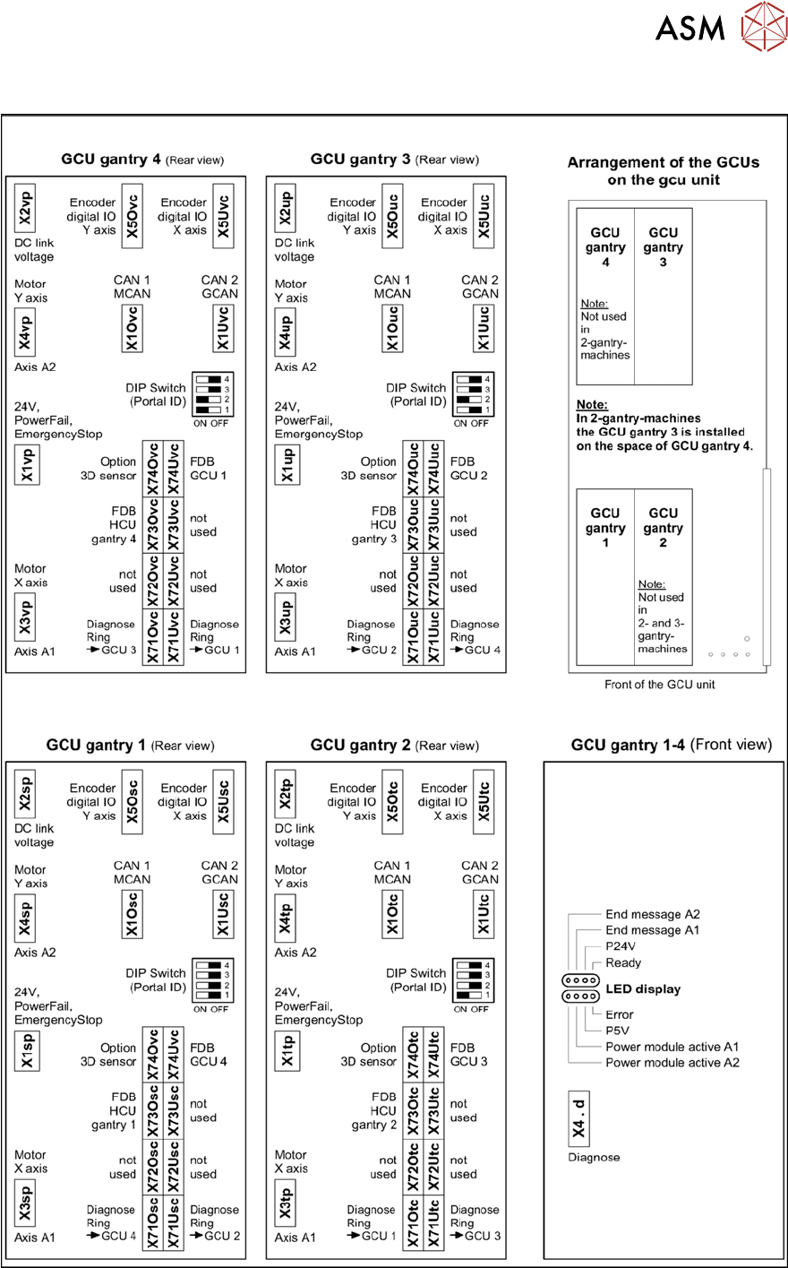
6.5.3 Overview of GCUs
Fig.234: Overview of GCUs
6 Gantries
6.5 GCU and MGCU
186 Service Manual SIPLACE X-Serie S 06/2019
DIP switch (gantry ID)
Switch Status Signal name Description
GCU1 GCU2 GCU3 GCU4
S1.1 ON/OFF Gantry_ID_0 OFF ON OFF ON
S1.2 ON/OFF Gantry_ID_1 OFF OFF ON ON
S1.3 ON/OFF Gantry_ID_2 OFF OFF OFF OFF
S1.4 ON/OFF Portal_ID_3 OFF OFF OFF OFF
LEDs
LED Color Status Signal name Description
H1 RD ON LED_ERROR Error display
H2 GN ON A1_LED_PM_ON_N Power module activated, axis 1
H3 GN ON A2_LED_PM_ON_N Power module activated, axis 2
H4 GN ON A1_LED_END End position signal, axis 1
H5 GN ON A2_LED_END End position signal, axis 2
H6 GN ON LED_READY Ready
H7 GN ON P24V +24VDC
H8 GN ON P5V +5VDC
6.5.4 Replacing the MGCU
NOTICE
MGCU or GCU
GCUs and MGCUs are not compatible. A GCU must always be replaced by a GCU and an
MGCU must be replaced by an MGCU.
Only MGCUs will be fitted from serial number Hxxxx.
GCUs are fitted up to serial number Gxxxx. Please read section 6.5.1 "Replacing the GCU" [}183].
Parts, equipment and tools
●
Positioning control for the gantry axes MGCU-3 (3 axes) [03103477-xx]
or
●
Positioning control for the gantry axes MGCU-2 (2 axes) [03117531-xx]
Overview
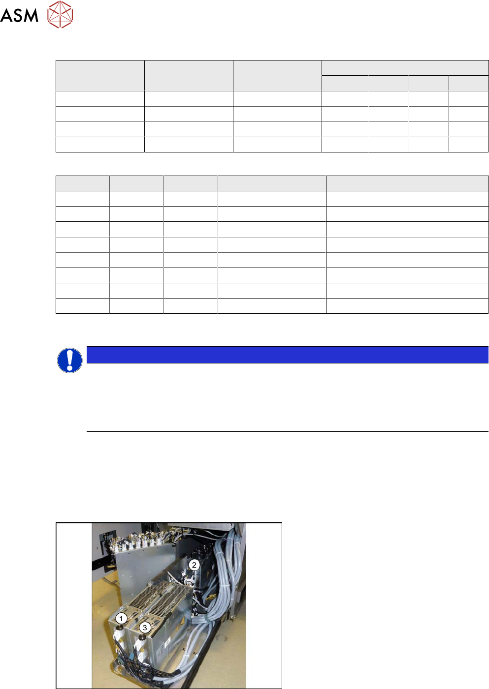
Fig.235: Overview of MGCUs
(1) to (3) MGCUs
The MGCUs are located in a rack unit
between locations 1 and 2.
MGCU 2 is fitted with the fans above and
MGCU 1 and 3 are fitted with the fans
below.
The MGCU type and the assignment of MGCUs to gantries differs according to the machine type.
6.5.6 "Overview of MGCUs" [}188]