00197042-04_SM_X-Serie-S_Customer_EN.pdf - 第193页
6 Gantries 6.6 HCU, MHCU, boards and camera Service Manual SIPLACE X-Serie S 06/2019 193 6.6.2 X base adapter C&P This board is used for C&P20x and CPP heads on SIPLACE X-Series S, SX4/DX4, TX and TX V2- Series m…
6 Gantries
6.6 HCU, MHCU, boards and camera
192 Service Manual SIPLACE X-Serie S 06/2019
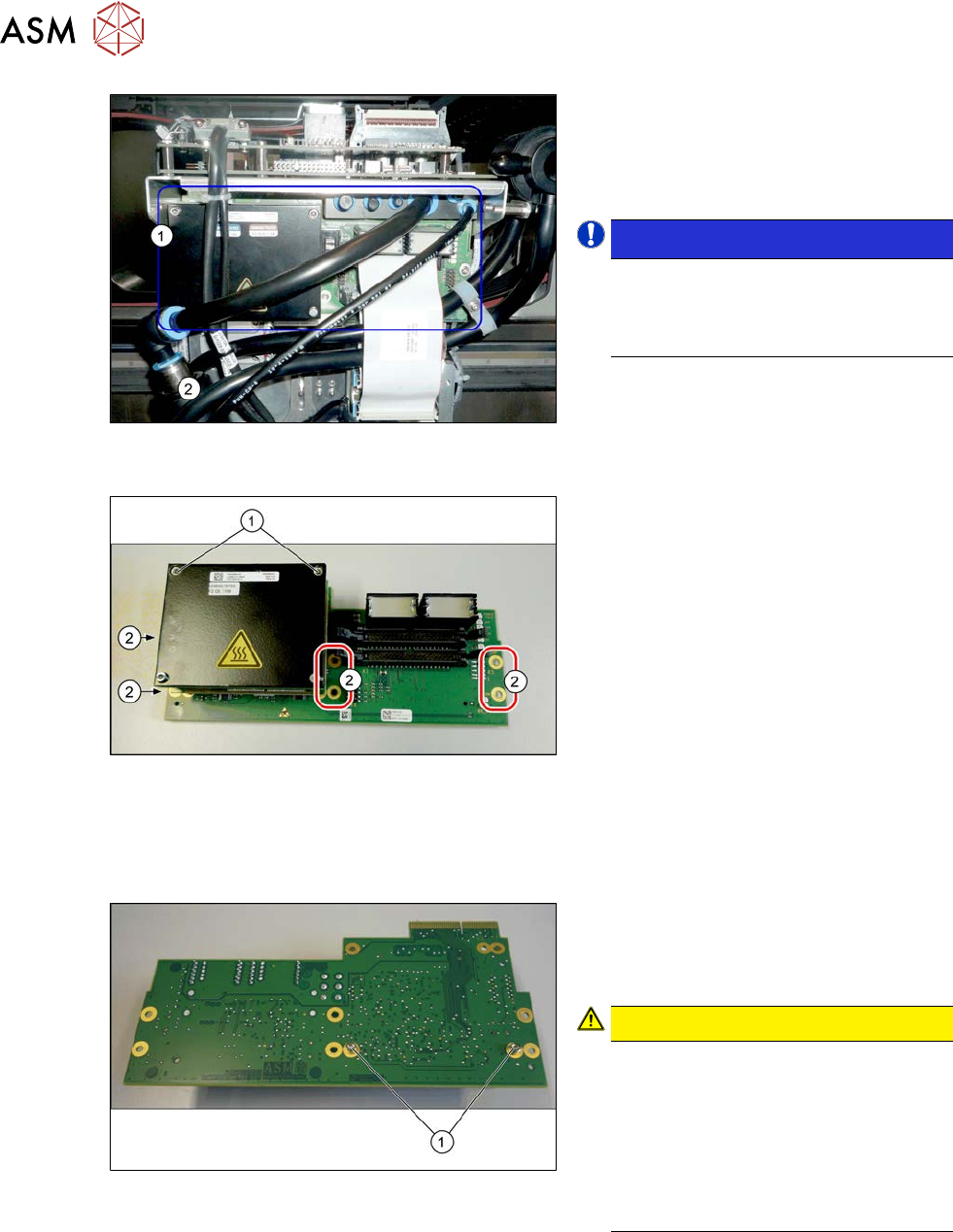
Fig.241: Head adapter HCU (example of C&P20A version
on an SX4 shown )
► Unplug all electrical connections to the
head adapter(1). You may want to
mark the positions of these connections
to make clear assignment easier later
on.
NOTICE!
SIPLACE X-Series S
You may need to also disconnect the
compressed air sensor on SIPLACE
C&P20P heads.
.
Fig.242: HCU
► Remove all the screws(2) fastening the
board.
► In addition, the board is fastened with
the topmost two HCU screws (1)in
each case. Remove these screws as
well.
► Carefully pull the board down and off.
Make sure that the head adapter board
is connected to the head interface via a
press-fit connection and two other
screws from below.
Converting the HCU
If you have ordered the base adapter without new MHCU(s), you will have to convert the MHCU(s)
from the old to the new basic adapter. To do so, proceed as follows:
Fig.243: Fastening screws on the back
► Remove the two screws(1) fastening
the MHCU on the back of the board
and carefully pull the MHCU off the
base adapter.
CAUTION!
Washers and pins
Make sure that you do not lose the
washers. Make a note of the number
of washers used for each screw, as
this may well differ. These will need to
be fitted back in again as well.
Make sure that you do not damage the
pins under the MHCU.
.
► Repeat the procedure, if needed, for the second MHCU (for Twin only).
Installation
► Follow the removal instructions in reverse order for installation. Also observe the following
instructions:
► Checking the embedded software and performing a download if needed.
6.9 "eSW Download (SW 70x)" [}202]
6 Gantries
6.6 HCU, MHCU, boards and camera
Service Manual SIPLACE X-Serie S 06/2019 193
6.6.2 X base adapter C&P
This board is used for C&P20x and CPP heads on SIPLACE X-Series S, SX4/DX4, TX and TX V2-
Series machines.
NOTICE
C&P20P
The X base adapter needs at least function level 08 for the C&P20 P head. In this case,
you may need longer flat ribbon cables.
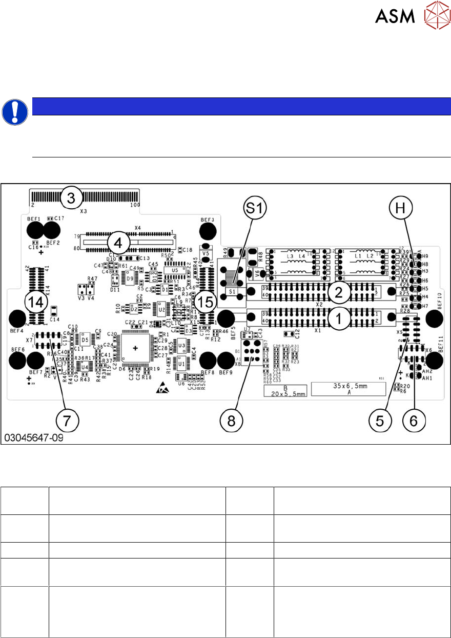
Version 09
Fig.244: X base adapter C&P [03045647‑xx]
Connections [03045647-09]
1, 2 X1-X2 Flat ribbon connection for CPP
or C&P20
3 X3 Connection to the head interface
board C700
4, 14, 15 X4, X14, X15 Connector for MHCU
(together with X14, X15)
5 X5 Test connector for FPGA
6 X6 Programming connector for FPGA 7 X7 Test connector MHCU
8 X8 Connectors for inlet vacuum
sensor (cable X1a)
H LED H3- H9
S1 Switch S1 intermediate circuit voltage
Z axis
40V C&P20 (switch top)
150V CPP(switch bottom)
6 Gantries
6.6 HCU, MHCU, boards and camera
194 Service Manual SIPLACE X-Serie S 06/2019
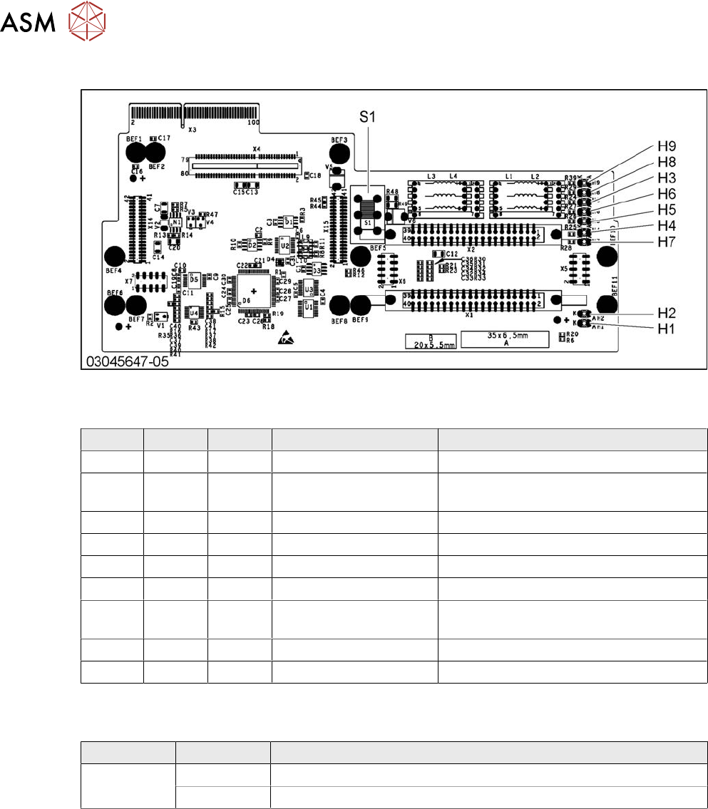
Version 05
Fig.245: X base adapter C&P
LED [03045647-05]
LED Color Status Signal name Description
H1 GN ON CO_SENSOR CO sensor active
H2 GN ON - The programming plug for the MHCU is
connected
H3 RD ON FPGA_TEST_6 1.5V power supply error
H4 RD ON FPGA_TEST_2 3.3V power supply error
H5 RD ON FPGA_TEST_4 5V power supply error
H6 RD ON FPGA_TEST_1 15V power supply error
H7 RD ON FPGA_TEST_3 DP power supply error, temp. without
function
H8 RD ON FPGA_TEST_5 24V power supply error
H9 RD ON POWERFAIL_LOCAL PowerFail on circuit board
The voltage monitors trigger as soon as the target voltage is exceeded or undershot by 5%.
Switch S1 [03045647-05]
Switch Status Function
S1 40V Intermediate circuit voltage for Z axis --> C&P20A/M/P
150V Intermediate circuit voltage for Z axis --> CPP
Switch S1 sets the intermediate circuit voltage for the Z axis
If the setting is incorrect, no damage will be done. However the MHCU will issue an error message.