00197042-04_SM_X-Serie-S_Customer_EN.pdf - 第195页
6 Gantries 6.6 HCU, MHCU, boards and camera Service Manual SIPLACE X-Serie S 06/2019 195 6.6.3 X Base adapter Twin This board is used for Twin heads on SIPLACE X-Series S, SX4/DX4, TX and TX V2-Series ma- chines. Fig.24…
6 Gantries
6.6 HCU, MHCU, boards and camera
194 Service Manual SIPLACE X-Serie S 06/2019
Version 05
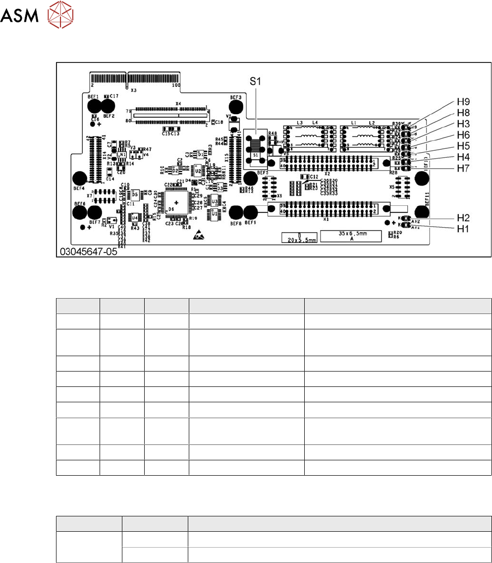
Fig.245: X base adapter C&P
LED [03045647-05]
LED Color Status Signal name Description
H1 GN ON CO_SENSOR CO sensor active
H2 GN ON - The programming plug for the MHCU is
connected
H3 RD ON FPGA_TEST_6 1.5V power supply error
H4 RD ON FPGA_TEST_2 3.3V power supply error
H5 RD ON FPGA_TEST_4 5V power supply error
H6 RD ON FPGA_TEST_1 15V power supply error
H7 RD ON FPGA_TEST_3 DP power supply error, temp. without
function
H8 RD ON FPGA_TEST_5 24V power supply error
H9 RD ON POWERFAIL_LOCAL PowerFail on circuit board
The voltage monitors trigger as soon as the target voltage is exceeded or undershot by 5%.
Switch S1 [03045647-05]
Switch Status Function
S1 40V Intermediate circuit voltage for Z axis --> C&P20A/M/P
150V Intermediate circuit voltage for Z axis --> CPP
Switch S1 sets the intermediate circuit voltage for the Z axis
If the setting is incorrect, no damage will be done. However the MHCU will issue an error message.
6 Gantries
6.6 HCU, MHCU, boards and camera
Service Manual SIPLACE X-Serie S 06/2019 195
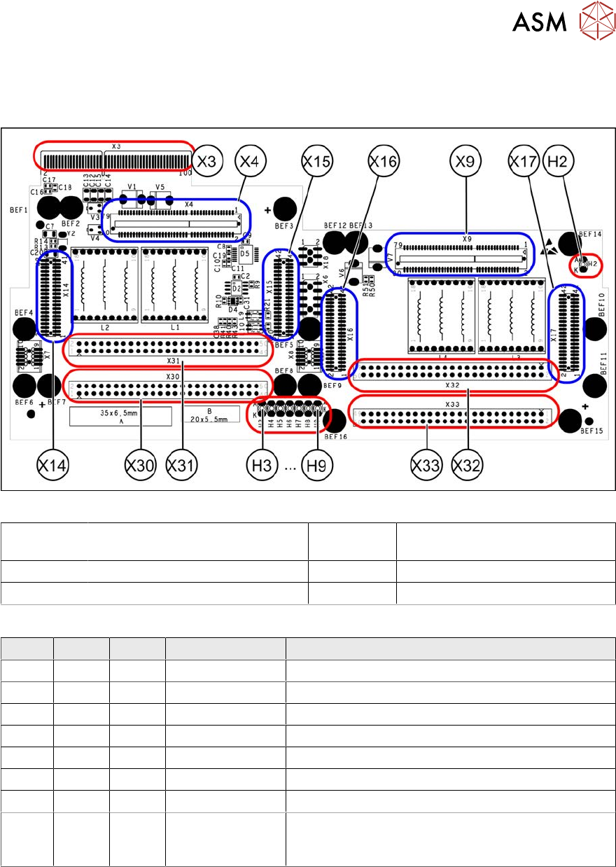
6.6.3 X Base adapter Twin
This board is used for Twin heads on SIPLACE X-Series S, SX4/DX4, TX and TX V2-Series ma-
chines.
Fig.246: X base adapter Twin [03062201-03]
X4 X14 X15 Connection for MHCU (Twin mod-
ule2)
X9 X16 X17 Connection for MHCU (Twin mod-
ule1)
X30 X31 Connections for Twin module 2 X32 X33 Connections for Twin module 1
X3 Connection on the head interface H2 to H9 LEDs (see below)
LED [03054879-03]
LED Color Status Signal name Description
H2 GN ON - HMCU2 programming connector connected
H3 RD ON FPGA_TEST_6 1.5VDC PowerFail
H4 RD ON FPGA_TEST_2 3.3VDC PowerFail
H5 RD ON FPGA_TEST_4 5VDC PowerFail
H6 RD ON FPGA_TEST_1 15VDC PowerFail
H7 RD ON FPGA_TEST_3 DP PowerFail, not used
H8 RD ON FPGA_TEST_5 24VDC PowerFail
H9 RD ON POWER-
FAIL_LOCAL
PowerFail board:
ON, when 1.5VDC, 3.3VDC, 5VDC and 15VDC are
outside the permissible tolerance
The voltage monitors trigger as soon as the target voltage is undershot by 5%.
6 Gantries
6.6 HCU, MHCU, boards and camera
196 Service Manual SIPLACE X-Serie S 06/2019
6.6.4 Replacing the connection cable from the Twin module to the HCU basic
adapter
Parts, equipment and tools
●
Cable / X connection cable Twin [03062202-xx]
Overview
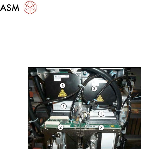
Fig.247: Cables
1. Connection cable from the Twin mod-
ule to the HCU basic adapter
2. Twin module
3. HCUs on the HCU base adapter
Removal
► Switch off the machine, disconnect it from the power supply and secure it to prevent
unauthorized reactivation. Observe the instructions in section 1.2 "Preparatory work..." [}16].
► Remove the two Twin modules form the machine (see 8.7 "Replacing the SIPLACE
Twin" [}320]).
► Remove the head adapter HCU from the machine and then dismantle the two HCUs. (see
6.6.1 "Replacing the MHCU, basic and head adapter" [}191]).
► Unplug both connection cables.
Installation
► Follow the removal instructions in reverse order for installation.
6.6.5 Replacing the PCB Camera
Parts, equipment and tools
●
SIPLACE X-Series S up to Gxxxx: PCB camera (type 34) 28 digital RK [03075363‑xx]
●
SIPLACE X-Series S from Hxxxx: PCB camera (type 34) 28 GigE [03101402‑xx]
●
Sealing varnish Loctite 241 [02101037-xx]