00197042-04_SM_X-Serie-S_Customer_EN.pdf - 第201页
6 Gantries 6.8 Sensor, motor and guide trolley Service Manual SIPLACE X-Serie S 06/2019 201 6.8.2 Replacing the X and Y Motor DANGER Danger of crushing The attraction force of the magnets is 400Nm. CAUTION Do not loosen…
6 Gantries
6.8 Sensor, motor and guide trolley
200 Service Manual SIPLACE X-Serie S 06/2019
6.8 Sensor, motor and guide trolley
6.8.1 Replacing the head plate sensors (temperature sensor)
Parts, equipment and tools
●
Gantry sensor module HCU [03071974-xx]
●
Gap fillers, where required / GTQ2100 d:4.6mm 7x16mm [03014285‑xx]
Overview
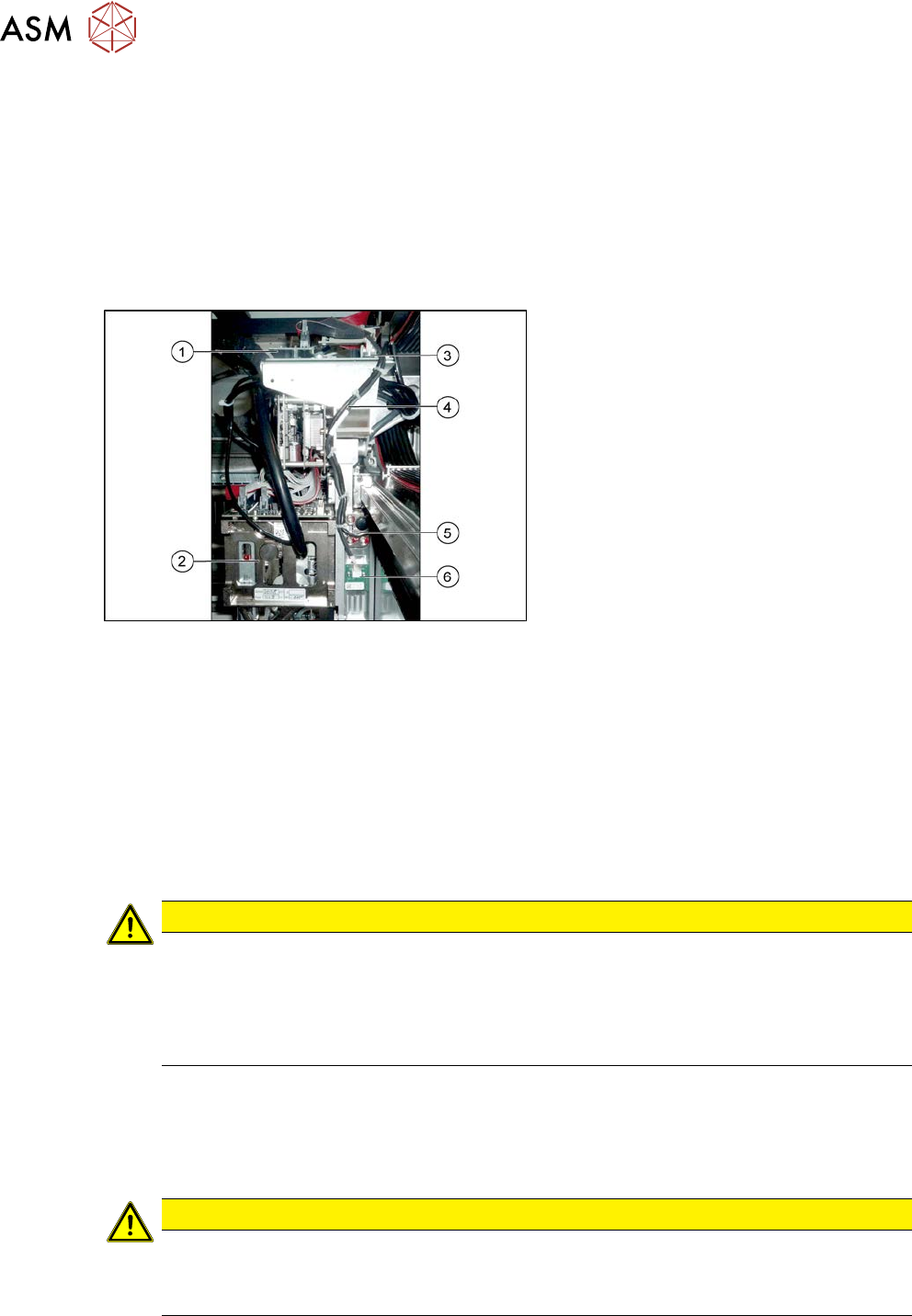
Fig.255: Overview of temperature sensor
1. Vision board
2. Placement head on gantry
3. Head interface
4. Cable from temperature sensor and in-
cremental encoder X axis to head inter-
face
5. The X axis incremental encoder
6. Temperature sensor
Removal
► Switch off the machine, disconnect it from the power supply and secure it to prevent
unauthorized reactivation.
1.2 "Preparatory work..." [}16]
► You can also dismantle the pin picker, if present, for better access.
9.6.1 "Replacing the Pin Picker Assembly" [}399]
► Unplug the cable from the head interface, unthread it and loosen all cable ties.
► Remove the two screws fastening the board and then pull it off.
CAUTION
Rubber foam
Under this board there is heat-conductive rubber foam (gap filler) or heat-conductive paste.
► Do not remove the heat-conductive rubber foam.
► The heat-conductive paste needs to be replaced during refitting. You may need to
remove the old heat-conductive paste, if it is still present.
Installation
► Fix the board into place with the two fastening screws.
► Insert the cable, thread through to the head interface and then connect. Replace any opened
cable ties.
CAUTION
Check how the cables are run!
► Make sure that the end stops (red buffers) do not rub against the cable of the board.
► Make sure that the cable for the board can not collide with the X axis end stopper.
6 Gantries
6.8 Sensor, motor and guide trolley
Service Manual SIPLACE X-Serie S 06/2019 201
6.8.2 Replacing the X and Y Motor
DANGER
Danger of crushing
The attraction force of the magnets is 400Nm.
CAUTION
Do not loosen the screws
Loosening the fastening screws leads to tension. This has a negative effect on the product
life.
NOTICE
SIPLACE Service
This task may only be performed by SIPLACE service technicians.
6.8.3 Replacing the Guide Trolley
DANGER
Danger of crushing
The attraction force of the magnets is 400Nm.
CAUTION
Do not loosen the screws
Loosening the fastening screws leads to tension. This has a negative effect on the product
life.
NOTICE
SIPLACE Service
This task may only be performed by SIPLACE service technicians.
6 Gantries
6.9 eSW Download (SW 70x)
202 Service Manual SIPLACE X-Serie S 06/2019
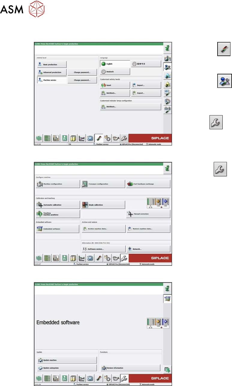
6.9 eSW Download (SW 70x)
Fig.256: Select operator level
► Select the
button, to open the
Configure, update and calibrate the
machine menu.
► Select the
button to open the
Check and set user settings menu.
► Switch over to the operator level Ma-
chine service.
ð The
button will be shown.
Fig.257: Service menu
► Click the
button to enter the Ser-
vice menu.
► Click on the Embedded software but-
ton.
Fig.258: Embedded software menu
Select the required function:
► Click on Update machine… to check
the entire machine and to perform an
eSW download for multiple subsystems
(see next picture).
► Click on Update subsystem… to se-
lect one subsystem, check and to per-
form an eSW download.
► Click on the button Version informa-
tion…, to view all versions of the sub-
systems, BIOS, application 1/2/3/5.