00197042-04_SM_X-Serie-S_Customer_EN.pdf - 第213页
7 Conveyor 7.3 Lifting Table Service Manual SIPLACE X-Serie S 06/2019 213 ► Switch off the machine, disconnect it from the power supply and secure it to prevent unauthorized reactivation. 1.2 "Preparatory work...&qu…
7 Conveyor
7.3 Lifting Table
212 Service Manual SIPLACE X-Serie S 06/2019
7.3 Lifting Table
DANGER
Press the EMERGENCY STOP!
Before performing adjustment work you must ensure that the lifting table has been secured
against movement!
7.3.1 Replacing the lifting table plate
Parts, equipment and tools
●
Single conveyor SIPLACE X-Series S:
Lifting table assembly 701 mm [03088801-xx]
●
Dual conveyor SIPLACE X-Series S:
Lifting table plate 1 assembly 350 mm [03088811-xx]
Lifting table plate 2 assembly 350 mm [03093910-xx]
Overview
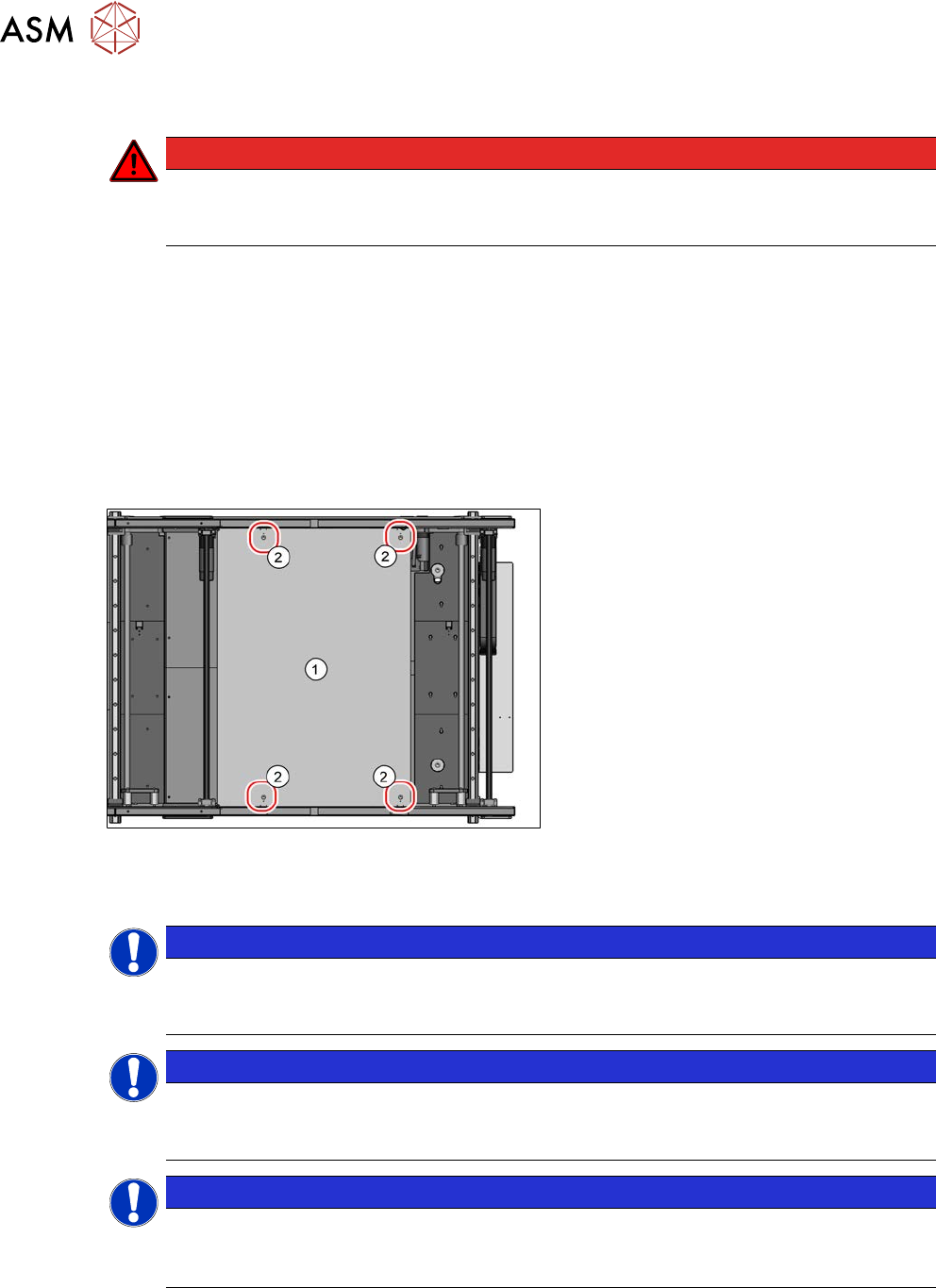
Fig.270: Lifting table plate
1. Lifting table plate
2. Fastening screws for lifting table plate
Removal
NOTICE
Single, dual conveyor
The replacement is shown in the diagram using the example of a lifting table unit for the
dual conveyor (DC). Replacement on a single conveyor (SC) follows the same procedure.
NOTICE
Does the lifting table stay in the top position?
If the lifting table remains in the top position and cannot be lowered, you will not be able to
dismantle the lifting table plate. In this case, call the SIPLACE Service team.
NOTICE
Lifting table plate guides
► Make sure that the lifting table guides are not mixed up. If you do, you will need to re-
set the parallelism of the lifting table plates.
► Use the software to move the conveyor sides into a position which allows you best access. As
an alternative, you can loosen the clamps for the relevant sides in dual conveyors.
7.2 "Loosening the Conveyor Side Clamps" [}207]
7 Conveyor
7.3 Lifting Table
Service Manual SIPLACE X-Serie S 06/2019 213
► Switch off the machine, disconnect it from the power supply and secure it to prevent
unauthorized reactivation.
1.2 "Preparatory work..." [}16]
► Remove the screws fastening the lifting table plate and remove the lifting table plate from the
machine. The lifting table plate is pinned to the table plate guides but can be easily pulled off.
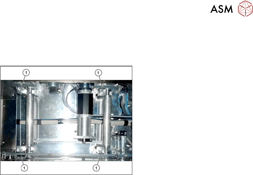
Fig.271: Lifting table plate guides
► Mark the positions of the lifting table
plate guides (1) to make it easier to refit
them later on. Make sure you do not
confuse these. If you do, you will need
to reset the parallelism of the lifting
table plates.
Installation
► Follow the removal instructions in reverse order for installation. Also observe the following
instructions:
●
The lifting table plate must slide in when inserted into the lifting table plate guidance pins.
●
Check the parallelism of the lifting table plate.
7.3.5 "Setting the Parallelism and Height of the Lifting Table Plate" [}217]
7 Conveyor
7.3 Lifting Table
214 Service Manual SIPLACE X-Serie S 06/2019
7.3.2 Replacing the lifting table motor
Parts, equipment and tools
●
BLDC motor BG65x50 assembly with cables and connectors [03088241-xx]
Overview
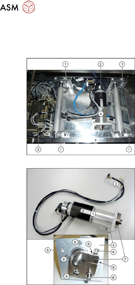
Fig.272: Lifting table when fitted
1. Lifting table plate guides
2. Lifting table motor
3. Conveyor control board
4. Screws fastening the retaining bracket
for the lifting table motor
Fig.273: Lifting table when not fitted
1. Lifting table motor
2. Electrical connections for the lifting
table motor
3. Retaining bracket for the lifting table
motor
4. Motor crank stopper for assembly in
conveyor lane 2 (left)
5. Alternative assembly position of stop-
per for assembly in conveyor lane 1
(right)
6. Connection to lifting table rods
7. Motor crank
8. Clamping screw for motor crank
9. Screws (4x) for fastening lifting table
motor to retaining bracket (partially
covered by the motor crank)