00197042-04_SM_X-Serie-S_Customer_EN.pdf - 第221页
7 Conveyor 7.4 Conveyor Drive Service Manual SIPLACE X-Serie S 06/2019 221 7.4.2 Replacing the Cables (Conveyor Drive) Parts, equipment and tools Select the relevant cable: ● Motor cable belt motor input lane 2 [03088863…

7 Conveyor
7.4 Conveyor Drive
220 Service Manual SIPLACE X-Serie S 06/2019
Installation
► Follow the removal instructions in reverse order for installation. Also observe the following
instructions:
●
Make sure that you do not fold or otherwise damage the toothed belt.
●
Make sure that the toothed belt is accurately positioned in the guidance on the motor shaft.
●
Tension the toothed belt with 10 to 15 Hz.
●
Secure the four screws fastening the conveyor drive to the drive bracket with Loctite 241 and
tighten these with a torque of 0.7 Nm.
●
Tighten the three screws fastening the plastic holder with a torque of 1.7 Nm. A washer must
be placed under the top screw.
●
Replace any cables ties, where needed.
Replace, in particular, the cable ties on the motor. Make sure that the cables, cable ties and,
in particular, the cable tie heads are not damaged on edges or rubbed against anything when
you adjust the conveyor sides.
Check for this along the whole width of the conveyor.
Also pay attention to the cable ties on the trailing cable and to the shield connection on the
conveyor drive.
●
When you tighten the movable roller, set the tension of the toothed belt correctly.
7.6.2 "Setting the belt tension (conveyor belt)" [}247]
●
Check if the belt drive and the drive unit are correctly aligned to each other. To do this, push
the conveyor sides together until you can still just reach the fastening screws. Check the con-
veyor drive for ease of movement by turning the hexagonal shaft. The hexagonal shaft must
run evenly and may not hit any part of the conveyor sides. You may need to loosen the con-
veyor drive and readjust it.
Perform this check along the whole width of the conveyor.
7 Conveyor
7.4 Conveyor Drive
Service Manual SIPLACE X-Serie S 06/2019 221
7.4.2 Replacing the Cables (Conveyor Drive)
Parts, equipment and tools
Select the relevant cable:
●
Motor cable belt motor input lane 2 [03088863-xx]
●
Sensor cable belt motor input lane 2 [03088871-xx]
NOTICE
Use compatible cables
Always use the cables [03088863-xx] or [03088871-xx]. These are compatible with the
cables listed below.
The following cables are not available as spare parts:
ü Motor cable belt motor input lane 1 [03088859-xx]
ü Motor cable belt motor placement area lane 1 [03088860-xx]
ü Motor cable belt motor output lane 1 [03088861-xx]
ü Motor cable belt motor placement area lane 2 [03088864-xx]
ü Motor cable belt motor output lane 2 [03088865-xx]
ü Sensor cable belt motor input lane 1 [03088866-xx]
ü Sensor cable belt motor placement area lane 1 [03088867-xx]
ü Sensor cable belt motor output lane 1 [03088868-xx]
ü Sensor cable belt motor placement area 1 lane 2 [03088872-xx]
ü Sensor cable belt motor output lane 2 [03088873-xx]
► Label the cable identically to the cable which is to be replaced. If the cable is too long,
stow the excess length in the conveyor base, near the connection. Fasten the cable
with cable ties, if needed.
●
Sealing varnish Loctite 241 [02101037-xx]
Removal
CAUTION
Do not loosen or remove the wrong screws
Make sure that you do not loosen or remove any other screws except those ones explicitly
mentioned. Loosening or removing other screws could lead to irreparable misalignment or
damage to the conveyor side.
► Use the software to move the conveyor sides into a position which allows you best access. As
an alternative, you can loosen the clamps for the relevant sides in dual conveyors.
7.2 "Loosening the Conveyor Side Clamps" [}207]
► Switch off the machine, disconnect it from the power supply and secure it to prevent
unauthorized reactivation.
1.2 "Preparatory work..." [}16]
► Remove the two screws fastening the cover plate above the connectors of the conveyor drive
and remove the cover plate. If you are not able to adequately reach the conveyor drive, dis-
mantle the conveyor drive.
7.4.1 "Replacing the conveyor drive" [}218]
► Unplug the cables and remove the cable ties on the drive.
► Unthread the cable from the conveyor side. Where necessary, dismantle the relevant clamp-
ing and guide rails.
Replacing the Clamping/Guide Rail
7 Conveyor
7.4 Conveyor Drive
222 Service Manual SIPLACE X-Serie S 06/2019
CAUTION
Make a note of the order in which the cables are run!
There is only limited space in the side section. The cables may therefore not be crossed
over.
Make a note of the order in which the cables are run in the side section, so that you can run
them neatly and correctly again later on.
CAUTION
Move the conveyor sides carefully!
The clamping and guide rails are a key stabilizing element for the conveyor side, which is
then less stable once they have been removed.
► When the clamps are released, take great care while you are moving the opened
sides.
Make sure that the rails are always pushed equally on the left and right.
Also make sure that you do not distort the rails.
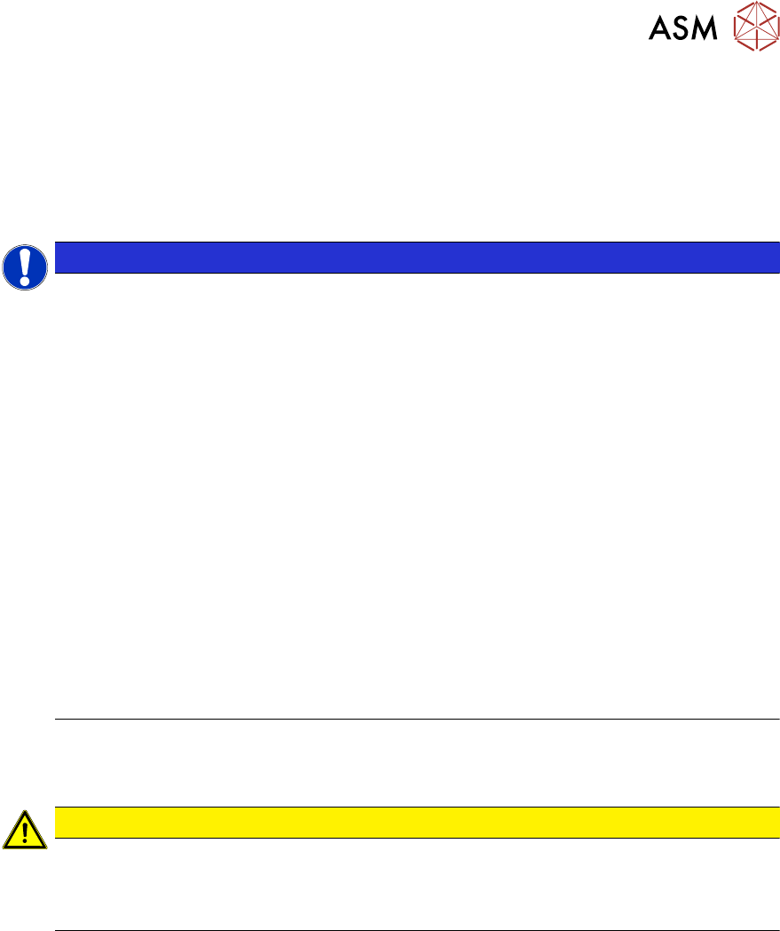
Fig.283: Trailing cable
► Remove the two screws(3) (Allen
key3) fastening the top retaining
plate(2) to the trailing cable(1).
► Remove the screws(4) (Allen key2)
fastening the bottom end of the trailing
cable.
NOTICE!
This is necessary in order to unthread
the cable out of the trailing cable.
.
► If needed, dismantle the cover
plates(5) over the cable connections.
► Open the trailing cable.
CAUTION
Protective tape, do not bend the fiber optic cable
There is also a protective tape in the trailing cable. This separates the cables from the fiber
optic cable.
► Make sure you do not bend the fiber optic cable. This will otherwise become cloudy
and no longer transmit the signal properly
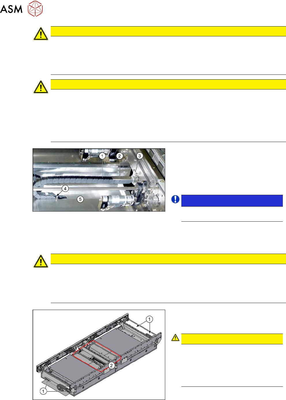
Fig.284: Conveyor controls
► Thread the cable out of the conveyor
side and the trailing cable as far as the
plug.
CAUTION!
Depending on the installation location,
the cable is either connected to the in-
put/output area(1) or to the conveyor
control(2) (under the covers).
You may want to mark the position, to
make clear assignment easier later on.
.