00197042-04_SM_X-Serie-S_Customer_EN.pdf - 第223页
7 Conveyor 7.4 Conveyor Drive Service Manual SIPLACE X-Serie S 06/2019 223 Installation ► Follow the removal instructions in reverse order for installation. Also observe the following instructions: – Check the setting fo…
7 Conveyor
7.4 Conveyor Drive
222 Service Manual SIPLACE X-Serie S 06/2019
CAUTION
Make a note of the order in which the cables are run!
There is only limited space in the side section. The cables may therefore not be crossed
over.
Make a note of the order in which the cables are run in the side section, so that you can run
them neatly and correctly again later on.
CAUTION
Move the conveyor sides carefully!
The clamping and guide rails are a key stabilizing element for the conveyor side, which is
then less stable once they have been removed.
► When the clamps are released, take great care while you are moving the opened
sides.
Make sure that the rails are always pushed equally on the left and right.
Also make sure that you do not distort the rails.
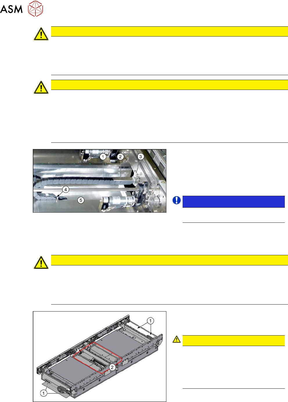
Fig.283: Trailing cable
► Remove the two screws(3) (Allen
key3) fastening the top retaining
plate(2) to the trailing cable(1).
► Remove the screws(4) (Allen key2)
fastening the bottom end of the trailing
cable.
NOTICE!
This is necessary in order to unthread
the cable out of the trailing cable.
.
► If needed, dismantle the cover
plates(5) over the cable connections.
► Open the trailing cable.
CAUTION
Protective tape, do not bend the fiber optic cable
There is also a protective tape in the trailing cable. This separates the cables from the fiber
optic cable.
► Make sure you do not bend the fiber optic cable. This will otherwise become cloudy
and no longer transmit the signal properly
Fig.284: Conveyor controls
► Thread the cable out of the conveyor
side and the trailing cable as far as the
plug.
CAUTION!
Depending on the installation location,
the cable is either connected to the in-
put/output area(1) or to the conveyor
control(2) (under the covers).
You may want to mark the position, to
make clear assignment easier later on.
.
7 Conveyor
7.4 Conveyor Drive
Service Manual SIPLACE X-Serie S 06/2019 223
Installation
► Follow the removal instructions in reverse order for installation. Also observe the following
instructions:
– Check the setting for the transmitter/receiver and correct if necessary
Setting and Correcting the Laser Light Barrier
– If you have loosened them:
Secure the four screws fastening the conveyor drive to the drive bracket with Loctite 241
and tighten these with a torque of 0.7 Nm.
– Replace any open cable ties.
Make sure that the cable ties and the heads of the cable ties do not rub against any parts
when you do this.
– Observe the installation instructions for the conveyor drive where necessary.
7.4.3 Replacing the drive shaft (conveyor drive)
Parts, equipment and tools
Fig.285: Drive shaft assembly
●
Drive shaft assembly SXa [03092349-
xx]
●
Bearing for hexagonal shaft SXa
(plastic bearing) – pack of 10
[03092024-xx]
●
Sealing varnish Loctite 241 [02101037-
xx]
Removal and installation
► Replacement of the drive shaft is follows the same procedure as replacement of the toothed
belt on the conveyor drive.
7.4.4 "Replacing the toothed belt (conveyor drive)" [}223]
7.4.4 Replacing the toothed belt (conveyor drive)
Parts, equipment and tools
●
Synchroflex toothed belt 6 AT3/150 [00355553-xx]
●
Bearing for hexagonal shaft SXa (plastic bearing) – pack of 10 [03092024-xx]
●
Sealing varnish Loctite 241 [02101037-xx]
Overview
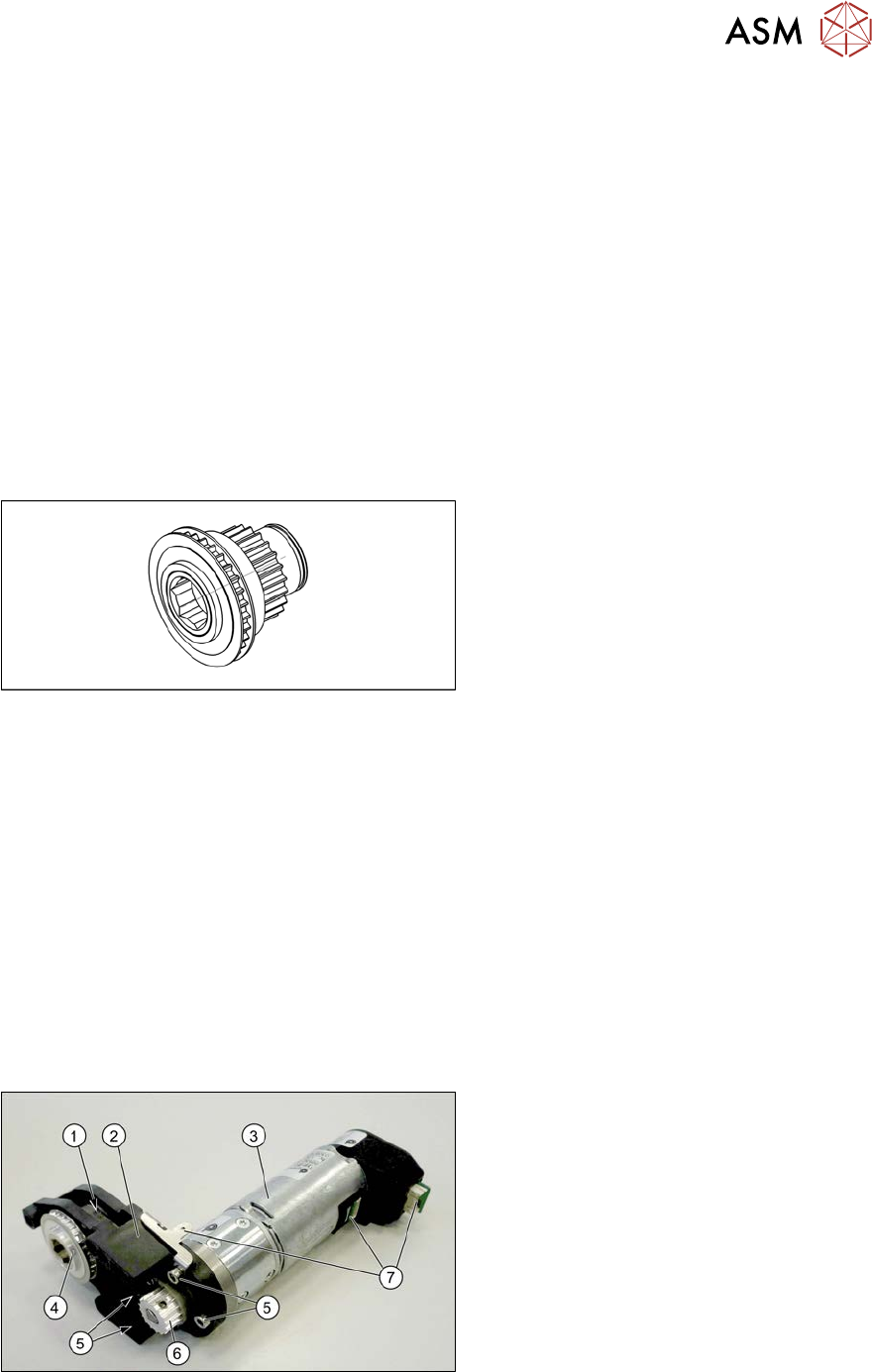
Fig.286: Conveyor drive
1. Toothed belt on conveyor drive
2. Drive bracket
3. Motor
4. Drive shaft
5. Four motor fastening screws in the
drive bracket
6. Motor shaft
7. Electrical connections (incl. shield con-
nection)
7 Conveyor
7.4 Conveyor Drive
224 Service Manual SIPLACE X-Serie S 06/2019
Fig.287: Drive shaft and bracket
1. Drive shaft with drive bracket, washers,
circlip and toothed belt
2. Motor fastening screws and shield con-
nection
Removal
CAUTION
Toothed belt
► Make sure that the toothed belt is not folded!
► Dismantle the conveyor drive. For more information, read section 7.4.1 "Replacing the con-
veyor drive" [}218].
NOTICE
Make a note of the order
You may want to make a note of the order in which the following parts are, to make it easier
to refit them later on. The number of washers may vary. Make sure that you fit the exact
number of these in the exact places.
► Open the circlip.
► Take off the washers.
► Pull the drive shaft out of the housing. You may need to apply slightly more force than usual to
remove the drive shaft.
► Remove the toothed belt.
Installation
► Follow the removal instructions in reverse order for installation. Also observe the following
instructions:
– Make sure that the toothed belt is not folded or otherwise damaged!
– Make sure that the toothed belt is not rubbed against anything.
– Tension the toothed belt with 10 to 15 Hz.
– Secure the four screws fastening the conveyor drive to the drive bracket with Loctite 241
and tighten these with a torque of 0.7 Nm.
– Replace any opened cable ties.
– Observe the installation instructions for the conveyor drive.