00197042-04_SM_X-Serie-S_Customer_EN.pdf - 第226页
7 Conveyor 7.5 Width Adjustment, Clamps and Cylinder Unit 226 Service Manual SIPLACE X-Serie S 06/2019 Fig.289: Removing the width adjustment drive ► Dismantle the cover plate (2) next to the width adjustment drive (1)…
7 Conveyor
7.5 Width Adjustment, Clamps and Cylinder Unit
Service Manual SIPLACE X-Serie S 06/2019 225
7.5 Width Adjustment, Clamps and Cylinder Unit
7.5.1 Replacing the drive (width adjustment)
Parts, equipment and tools
●
Drive unit of width adjustment assembly SXa [03092543-xx]
●
If needed, bearing for hexagonal shaft SXa (plastic bearing) – pack of 10 [03092024-xx]
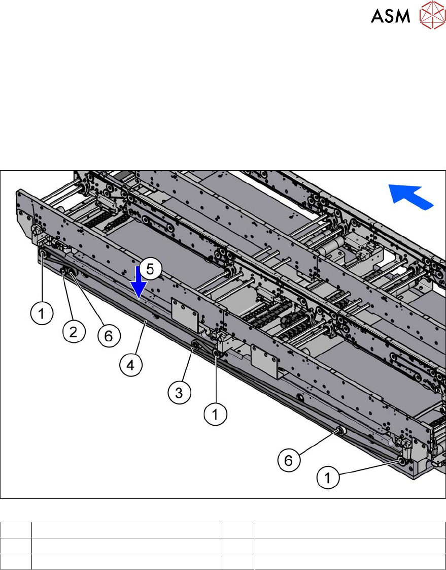
Overview
Fig.288: Overview of width adjustment
1 Cylinder units 2 Width adjustment drive
3 Movable idler pulley 4 Toothed belt of width adjustment
5 Measurement point for belt tension 6 Idler pulley
Removal
► Use the software to move the conveyor sides into a position which allows you best access. As
an alternative, you can loosen the clamps for the relevant sides in dual conveyors.
7.2 "Loosening the Conveyor Side Clamps" [}207]
► Switch off the machine, disconnect it from the power supply and secure it to prevent
unauthorized reactivation.
1.2 "Preparatory work..." [}16]
► Move the cylinder units as far as the end stop on one side of the conveyor. To do this, move
the toothed belt of the width adjustment.
► Dismantle the lifting table plate over the width adjustment drive.
7.3.1 "Replacing the lifting table plate" [}212]
► Dismantle the cover over the conveyor control at the movable idler pulley.
► Loosen the movable idler pulleyfor the width adjustment toothed belt (SW10).
7 Conveyor
7.5 Width Adjustment, Clamps and Cylinder Unit
226 Service Manual SIPLACE X-Serie S 06/2019
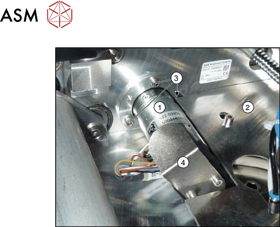
Fig.289: Removing the width adjustment drive
► Dismantle the cover plate(2) next to
the width adjustment drive (1).
► Remove the screws(3) fastening the
width adjustment drive.
► Remove the screws fastening the cover
plate(4) over the connectors of the
width adjustment drive.
► Unplug the connector from the width adjustment drive. You may want to mark the position, to
make clear assignment easier later on.
Installation
► Follow the removal instructions in reverse order for installation. Also observe the following
instructions:
●
Carefully thread in the toothed belt. To do this, carefully lift the toothed belt a little ( e.g. with
the shorter end of an Allen key).
●
Make sure that the cylinder units are parallel.
7.10.2 "Setting the Parallelism of the Conveyor Sides and Adjustment Units" [}298]
●
Set the correct belt tension.
7.5.2.1 "Setting the belt tension (width adjustment)" [}228]
7 Conveyor
7.5 Width Adjustment, Clamps and Cylinder Unit
Service Manual SIPLACE X-Serie S 06/2019 227
7.5.2 Replacing the toothed belt (width adjustment)
Parts, equipment and tools
●
Toothed belt BRECOFLEX 12 T5/3950 [03087325-xx]
●
Bearing for hexagonal shaft SXa (plastic bearing) – pack of 10 [03092024-xx]
Overview
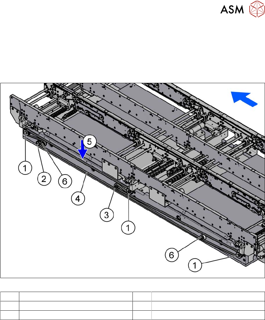
Fig.290: Overview of width adjustment
1 Cylinder units 2 Width adjustment drive
3 Movable idler pulley 4 Toothed belt of width adjustment
5 Measurement point for belt tension 6 Idler pulley
Removal
► Use the software to move the conveyor sides into a position which allows you best access. As
an alternative, you can loosen the clamps for the relevant sides in dual conveyors.
7.2 "Loosening the Conveyor Side Clamps" [}207]
► Switch off the machine, disconnect it from the power supply and secure it to prevent
unauthorized reactivation.
1.2 "Preparatory work..." [}16]
► Move the cylinder units as far as the end stop on one side of the conveyor. To do this, move
the toothed belt of the width adjustment.
► Dismantle the cover over the conveyor control.
► Loosen the movable idler pulleyfor the width adjustment toothed belt on the inside of the con-
veyor. (Open-ended wrench, size 10)
► Unthread the toothed belt.