00197042-04_SM_X-Serie-S_Customer_EN.pdf - 第232页
7 Conveyor 7.5 Width Adjustment, Clamps and Cylinder Unit 232 Service Manual SIPLACE X-Serie S 06/2019 Installation ► Follow the removal instructions in reverse order for installation. Also observe the following instruct…
7 Conveyor
7.5 Width Adjustment, Clamps and Cylinder Unit
Service Manual SIPLACE X-Serie S 06/2019 231
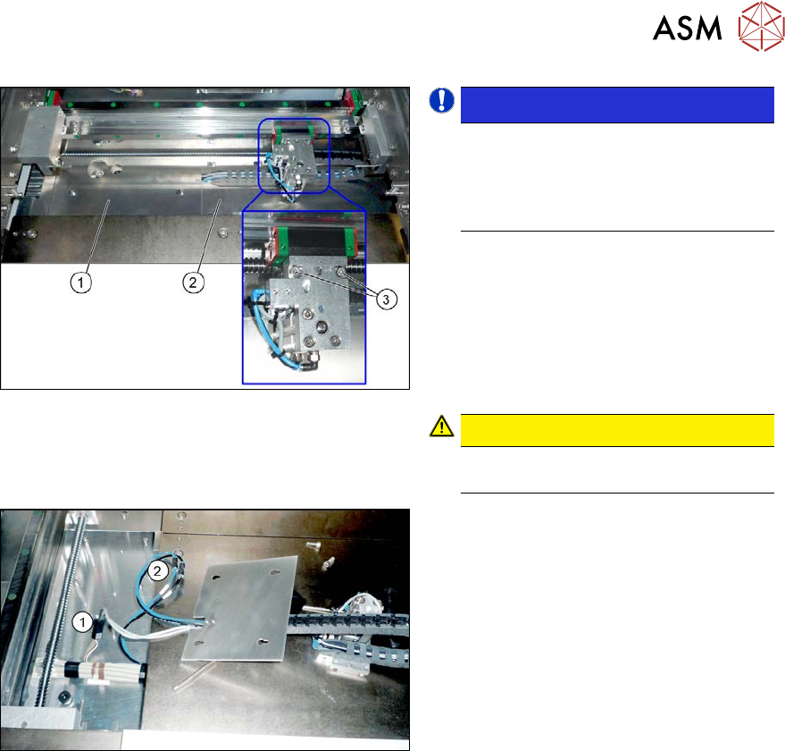
Fig.293: Cylinder unit (example of SIPLACE SX1/SX2
shown)
NOTICE!
The cover plates (1) and (2) can only
be dismantled if the cylinder unit is not
above it. You may need to gently pull
on the width adjustment belt to move
the cylinder unit.
.
► Remove the screws fastening the cover
plate (1).
► Remove the screws fastening the cover
plate (2).
► Remove the two screws fastening the
cylinder unit (3). You can now lift the
cylinder unit up and off.
CAUTION!
The cylinder unit is pinned and can be
stiff to move.
.
Fig.294: Connections (example of SIPLACE SX1/SX2
shown)
► Disconnect the cylinder unit from the
electrical(1) and pneumatic(2) sup-
plies. These are located under the
cover plates or in the intermediate con-
veyor, at the conveyor control.
You may want to mark their positions,
to make clear assignment easier later
on.
► Take the cylinder unit out of the machine, together with the cover plate.
► Remove the screws fastening the trailing cable to the cover plate.
7 Conveyor
7.5 Width Adjustment, Clamps and Cylinder Unit
232 Service Manual SIPLACE X-Serie S 06/2019
Installation
► Follow the removal instructions in reverse order for installation. Also observe the following
instructions:
– Make sure that the cable is run correctly and does not rub against any parts.
– Make sure that the cylinder unit lies flush against the trolley when you screw it into place.
(See also the following diagram)
– Replace any open cable ties.
Make sure that the cable ties and the heads of the cable ties do not rub against any parts
when you do this.
– After installation, make sure that the cylinder piston does not protrude above the other
parts. You might need to place washers between the adapter plate and the cylinder.
– After installation, check whether the cylinder unit can be moved along the entire width of
the conveyor. Make sure that there are no interfering edges etc.
– Check the distance to the clamping units. (see 7.5.9 "Information About the Clamping Unit
Versions (DC Only)" [}237]).
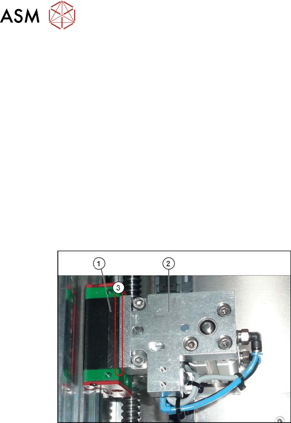
Fig.295: Fitting the cylinder unit
1. Trolley
2. Cylinder unit
3. The cylinder unit must lie flush against
the carriage. Make sure that there is no
gap in-between.
► Recalibrate all conveyor sides for lane1 and2 (both in Dual conveyor right mode and in
Dual conveyor left mode).
7 Conveyor
7.5 Width Adjustment, Clamps and Cylinder Unit
Service Manual SIPLACE X-Serie S 06/2019 233
7.5.5 Replacing the proximity switch for the cylinder unit (width adjustment)
Parts, equipment and tools
●
New: proximity switch SME-8M-DS-24V-K-2.5 [03100139-xx]
or
Old: proximity switch SME-8-K-LED-24 [00343651-xx]
Overview
Fig.296: Sensor system (example of SX1/SX2 shown)
1. Proximity switch for the cylinder
2. Grub screw for fastening the sensor
3. Inductive sensor (position detection for
conveyor side)
Removal
► Remove the cylinder unit. Please read section 7.5.4 "Replacing the Cylinder Unit (Width Ad-
justment)" [}230].
► Remove the screw fastening the proximity switch.
► Loosen the screw fastening the sensor.
► Open the trailing cable and remove the sensor cable.
Installation
► Follow the removal instructions in reverse order for installation. Also observe the following
instructions:
– Dismantle the connector from the old proximity switch and fit it in the new proximity switch.
To do this, release the crimp connections on the old proximity switch from the connector
and insert them into the new proximity switch. Note the correct assignment for this!
– Fix the new proximity switch to the correct position (see below).
– The sensor must lie flush against the surface of the cylinder unit.
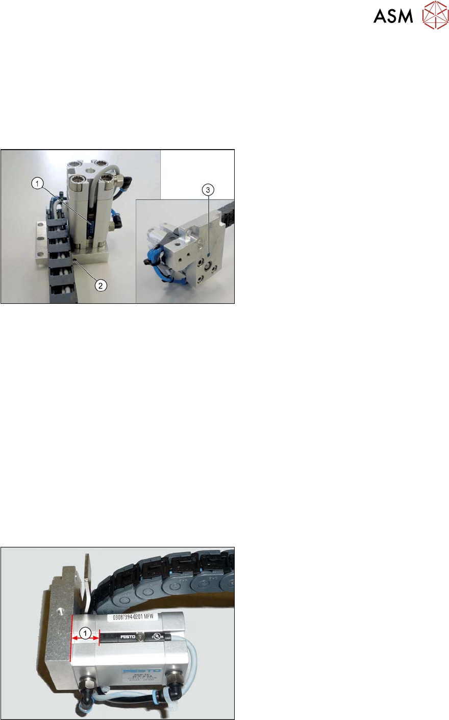
Fig.297: Setting the proximity switch
1. Distance between the lower edge of the
head plate and the upper edge of the
proximity switch:
●
13 mm for new proximity switch
SME-8M-DS-24V-K-2.5 [03100139-xx]
●
10 mm for old proximity switch SME-8-
K-LED-24 [00343651-xx]