00197042-04_SM_X-Serie-S_Customer_EN.pdf - 第234页
7 Conveyor 7.5 Width Adjustment, Clamps and Cylinder Unit 234 Service Manual SIPLACE X-Serie S 06/2019 7.5.6 Replacing the inductive sensor for side detection on the cylinder unit (width adjustment) Overview Fig.298: Pr…
7 Conveyor
7.5 Width Adjustment, Clamps and Cylinder Unit
Service Manual SIPLACE X-Serie S 06/2019 233
7.5.5 Replacing the proximity switch for the cylinder unit (width adjustment)
Parts, equipment and tools
●
New: proximity switch SME-8M-DS-24V-K-2.5 [03100139-xx]
or
Old: proximity switch SME-8-K-LED-24 [00343651-xx]
Overview
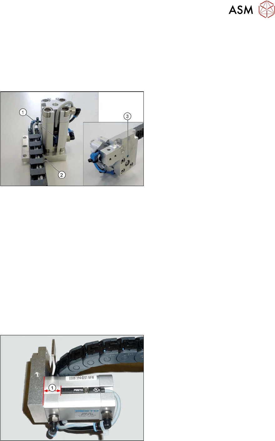
Fig.296: Sensor system (example of SX1/SX2 shown)
1. Proximity switch for the cylinder
2. Grub screw for fastening the sensor
3. Inductive sensor (position detection for
conveyor side)
Removal
► Remove the cylinder unit. Please read section 7.5.4 "Replacing the Cylinder Unit (Width Ad-
justment)" [}230].
► Remove the screw fastening the proximity switch.
► Loosen the screw fastening the sensor.
► Open the trailing cable and remove the sensor cable.
Installation
► Follow the removal instructions in reverse order for installation. Also observe the following
instructions:
– Dismantle the connector from the old proximity switch and fit it in the new proximity switch.
To do this, release the crimp connections on the old proximity switch from the connector
and insert them into the new proximity switch. Note the correct assignment for this!
– Fix the new proximity switch to the correct position (see below).
– The sensor must lie flush against the surface of the cylinder unit.
Fig.297: Setting the proximity switch
1. Distance between the lower edge of the
head plate and the upper edge of the
proximity switch:
●
13 mm for new proximity switch
SME-8M-DS-24V-K-2.5 [03100139-xx]
●
10 mm for old proximity switch SME-8-
K-LED-24 [00343651-xx]
7 Conveyor
7.5 Width Adjustment, Clamps and Cylinder Unit
234 Service Manual SIPLACE X-Serie S 06/2019
7.5.6 Replacing the inductive sensor for side detection on the cylinder unit (width
adjustment)
Overview
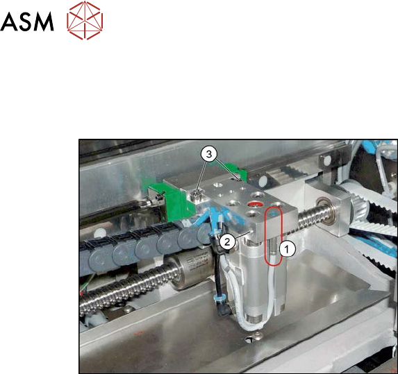
Fig.298: Proximity switch on the cylinder unit
1. Proximity switch on the cylinder unit
Proximity switch 3RG4/4.0mm/
sn=0.8mm/1S [00304908‑xx]
2. Screw fastening the proximity switch
3. Screw fastening the cylinder unit to the
carriage
Removal
► Removal of the proximity switch is the same as that of the sensor system. Please read section
7.5.5 "Replacing the proximity switch for the cylinder unit (width adjustment)" [}233].
► Loosen the screw fastening the proximity switch and pull the proximity switch out of the cylin-
der unit.
Installation
► Follow the removal instructions in reverse order for installation. Also observe the following
instructions:
– Dismantle the connector from the old inductive sensor and fit it in the new inductive sensor.
To do this, release the crimp connections on the old inductive sensor from the connector
and insert them into the new inductive sensor. Note the correct assignment for this!
– Turn the proximity switch so that the LED is visible when fitted.
– Make sure that the proximity switch does not protrude over the basic structure of the cylin-
der unit. Check this when the machine is switched on. To do this, move a conveyor side
over the cylinder unit. The LED should only shine when you do this. The gap between the
conveyor side clamping unit and the proximity switch on the cylinder unit must be at least
0.3 mm.
Check whether this gap is kept for all conveyor sides and that the proximity switch reliably
recognizes all conveyor sides. You can check this with the LED, when the machine is
switched on. Simply move the width adjustment manually along the conveyor with the help
of the toothed belt.
– Recalibrate all conveyor sides for lane1 and2 (both in Dual conveyor right mode and in
Dual conveyor left mode).
7 Conveyor
7.5 Width Adjustment, Clamps and Cylinder Unit
Service Manual SIPLACE X-Serie S 06/2019 235
7.5.7 Replacing the short-stroke cylinder (width adjustment)
Parts, equipment and tools
●
Compact cylinder ADN-16-20-P-A-SA [03100045-xx] or
short-stroke ADVU-16-20-P-A-SA [00356862-xx]
Overview
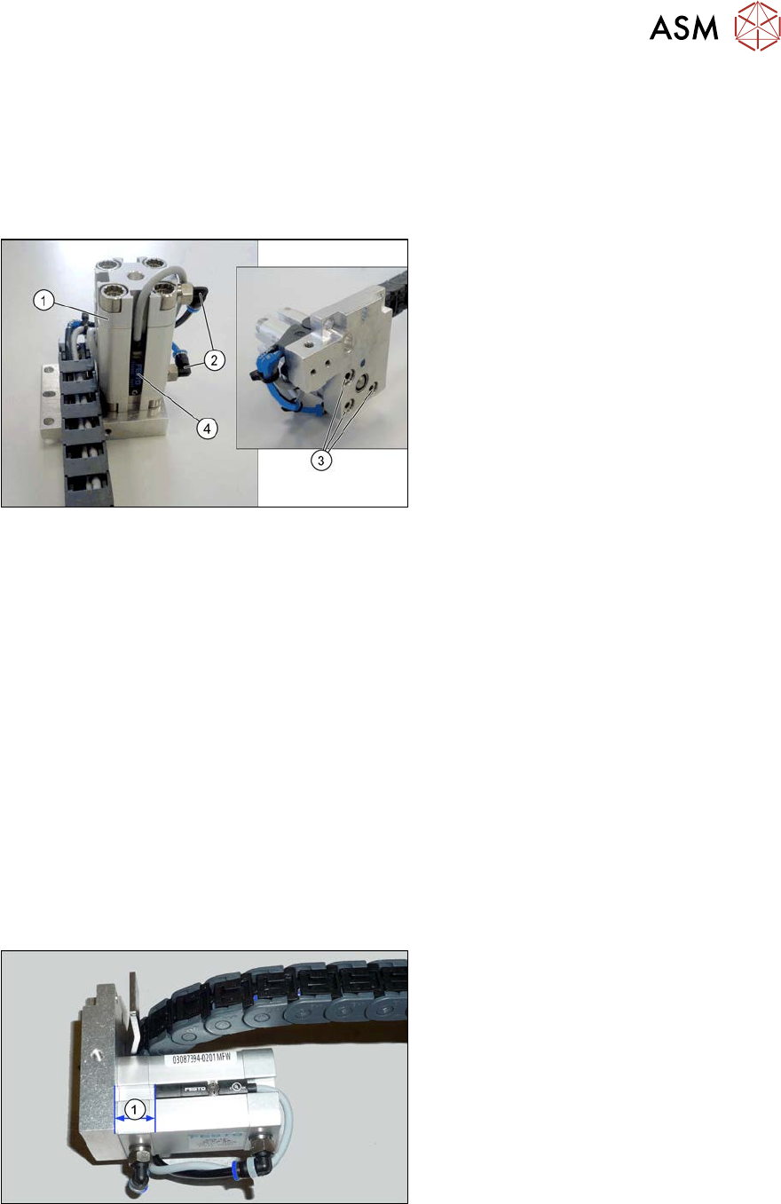
Fig.299: Overview of short-stroke cylinder
1. Short stroke cylinder
2. Pneumatic connections on short-stroke
cylinder
3. Screws (3x) fastening the short-stroke
cylinder
4. Proximity switch
Removal
► Remove the cylinder unit. Please read section 7.5.4 "Replacing the Cylinder Unit (Width Ad-
justment)" [}230].
► Unplug the pneumatic connections to the short-stroke cylinder. If necessary, mark their posi-
tions to make clear assignment easier later on.
► Remove the screw fastening the proximity switch.
► Remove the three screws holding the short-stroke cylinder.
Installation
► Follow the removal instructions in reverse order for installation. Also observe the following
instructions:
– Fasten the proximity switch to the old short-stroke cylinder. Follow the diagram below for
this.
– Make sure you have the pneumatic connections in the correct places. These pneumatic
connections must be on the side facing away from the trailing cable (see diagram above).
– Make sure that the inserted parallel pin does not protrude above the base unit.
Fig.300: Setting the proximity switch
Set the distance between the proximity
switch and the upper edge of the short-
stroke cylinder. This depends on the short-
stroke cylinder fitted:
●
Distance 13 mm for "short-stroke cyl-
inder ADN-16-20-P-A-
SA" [03100045‑xx]
●
Distance 10 mm for "short-stroke cyl-
inder ADVU-16-20-P-A-
SA" [00356862‑xx]