00197042-04_SM_X-Serie-S_Customer_EN.pdf - 第236页
7 Conveyor 7.5 Width Adjustment, Clamps and Cylinder Unit 236 Service Manual SIPLACE X-Serie S 06/2019 7.5.8 Replacing the valve terminal for cylinders (width adjustment) Parts, equipment and tools ● Valve terminal 3-fol…
7 Conveyor
7.5 Width Adjustment, Clamps and Cylinder Unit
Service Manual SIPLACE X-Serie S 06/2019 235
7.5.7 Replacing the short-stroke cylinder (width adjustment)
Parts, equipment and tools
●
Compact cylinder ADN-16-20-P-A-SA [03100045-xx] or
short-stroke ADVU-16-20-P-A-SA [00356862-xx]
Overview
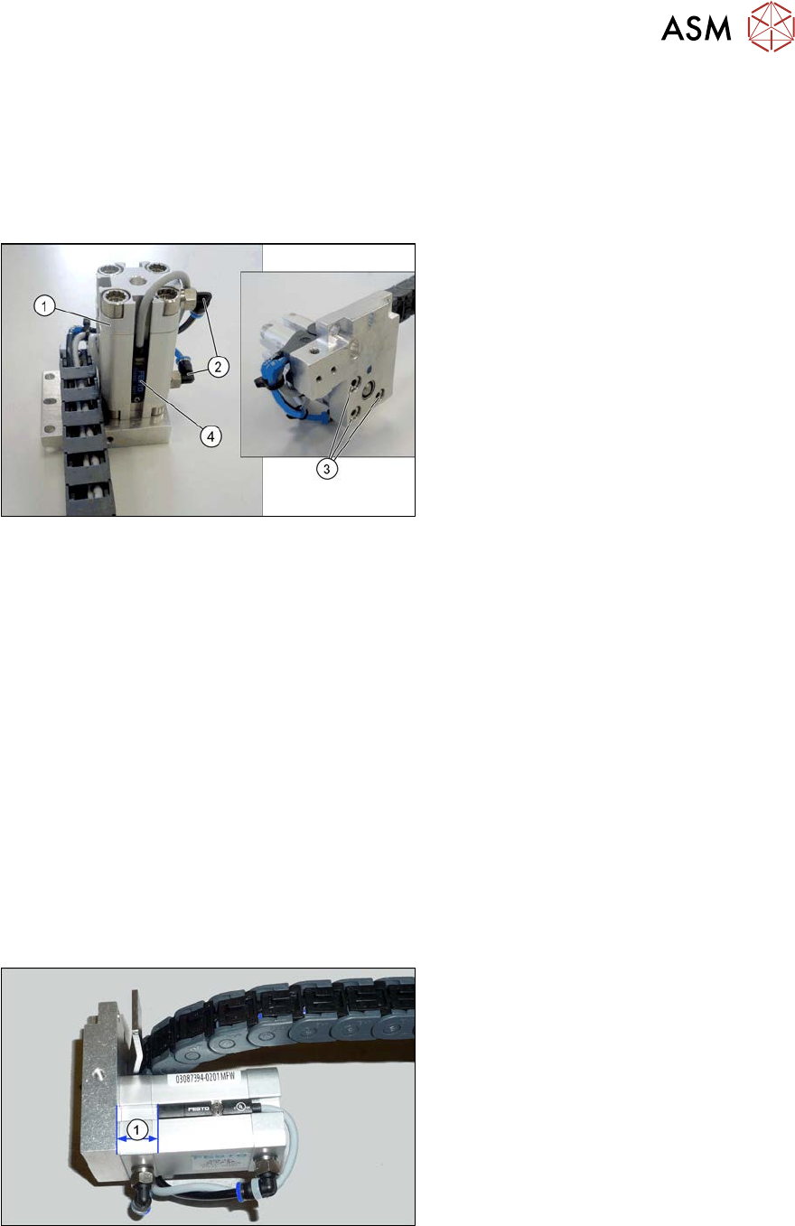
Fig.299: Overview of short-stroke cylinder
1. Short stroke cylinder
2. Pneumatic connections on short-stroke
cylinder
3. Screws (3x) fastening the short-stroke
cylinder
4. Proximity switch
Removal
► Remove the cylinder unit. Please read section 7.5.4 "Replacing the Cylinder Unit (Width Ad-
justment)" [}230].
► Unplug the pneumatic connections to the short-stroke cylinder. If necessary, mark their posi-
tions to make clear assignment easier later on.
► Remove the screw fastening the proximity switch.
► Remove the three screws holding the short-stroke cylinder.
Installation
► Follow the removal instructions in reverse order for installation. Also observe the following
instructions:
– Fasten the proximity switch to the old short-stroke cylinder. Follow the diagram below for
this.
– Make sure you have the pneumatic connections in the correct places. These pneumatic
connections must be on the side facing away from the trailing cable (see diagram above).
– Make sure that the inserted parallel pin does not protrude above the base unit.
Fig.300: Setting the proximity switch
Set the distance between the proximity
switch and the upper edge of the short-
stroke cylinder. This depends on the short-
stroke cylinder fitted:
●
Distance 13 mm for "short-stroke cyl-
inder ADN-16-20-P-A-
SA" [03100045‑xx]
●
Distance 10 mm for "short-stroke cyl-
inder ADVU-16-20-P-A-
SA" [00356862‑xx]
7 Conveyor
7.5 Width Adjustment, Clamps and Cylinder Unit
236 Service Manual SIPLACE X-Serie S 06/2019
7.5.8 Replacing the valve terminal for cylinders (width adjustment)
Parts, equipment and tools
●
Valve terminal 3-fold [03092667-xx]
Overview
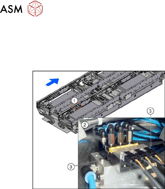
Fig.301: Overview of valve terminal
1. The valve terminal is located in the
center, between location 2 and 3, under
the lifting table plates.
2. Valve terminal
3. Fastening screws (2x) for valve ter-
minal
Removal
► Use the software to move the conveyor sides into a position which allows you best access. As
an alternative, you can loosen the clamps for the relevant sides in dual conveyors.
7.2 "Loosening the Conveyor Side Clamps" [}207]
► Switch off the machine, disconnect it from the power supply and secure it to prevent
unauthorized reactivation.
1.2 "Preparatory work..." [}16]
► Switch off the compressed air supply
5.2 "Disabling the compressed air supply" [}134]
► Remove the screws fastening the lifting table plate at location 3 and remove the lifting table
plate.
7.3.1 "Replacing the lifting table plate" [}212]
► Remove the two screws fastening the valve terminal.
► Disconnect the valve terminal from the power and pneumatic connections. You might like to
mark their positions to make clear assignment easier later on.
► Take the valve terminal out of the machine.
Installation
► Follow the removal instructions in reverse order for installation. Also observe the following
instructions:
– Compare the old and the new valve terminal. You may sometimes have to refit the silencer
and pneumatic connections from the old valve terminal on the new valve terminal.
– Replace any opened cable ties.
7 Conveyor
7.5 Width Adjustment, Clamps and Cylinder Unit
Service Manual SIPLACE X-Serie S 06/2019 237
7.5.9 Information About the Clamping Unit Versions (DC Only)
NOTICE
Old/new clamping unit
A combination of old and new clamping units is possible.
Before installing a new clamping unit (version 2), make sure that your machine has
SW706.1 SP1 with Hotfix 4 or higher.
Overview
There are numerous versions of the clamping units. These differ, above all by the sensor flag:
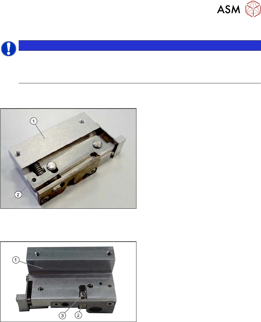
Fig.302: Clamp version 1
Version 1
1. Clamp
2. An M3x16 mm screw can be inserted
here to permanently release the clamp.
► For details about replacing the clamping units (version 1), read section 7.5.10 "Replacing the
Clamping Unit (Version 1) (DC Only)" [}238].
Fig.303: Clamp version 2
Version 2
1. Clamp
2. Sensor switch
3. Fastening screw for sensor switch
► For details about replacing the clamping units (version 2), read section 7.5.11 "Replacing the
Clamping Unit (Version 2) (DC Only)" [}242].