00197042-04_SM_X-Serie-S_Customer_EN.pdf - 第240页
7 Conveyor 7.5 Width Adjustment, Clamps and Cylinder Unit 240 Service Manual SIPLACE X-Serie S 06/2019 Fig.307: Fitting the clamp ► Place a 0.3 mm feeler gauge (3) between the clamp (1) and cylinder unit (2) . Two feele…
7 Conveyor
7.5 Width Adjustment, Clamps and Cylinder Unit
Service Manual SIPLACE X-Serie S 06/2019 239
Removal
► Use the software to move the conveyor sides into a position which allows you best access.
The sides must move freely. Fix all 3 clamping units into place with one screw each, so that
the clamp is not able to exert any force onto the conveyor side.
7.2 "Loosening the Conveyor Side Clamps" [}207]
► Switch off the machine, disconnect it from the power supply and secure it to prevent
unauthorized reactivation.
1.2 "Preparatory work..." [}16]
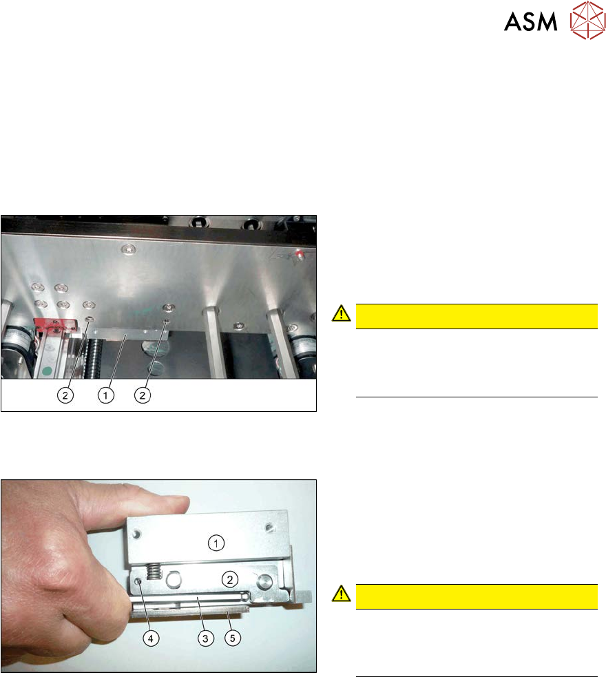
Fig.305: Removing the clamp
► Remove the two screws (2) fastening
the clamp(1). These are on the side of
the conveyor side which faces away
from the clamp. Make sure that you do
not loosen any other screws!
CAUTION!
The screws fastening the clamps may
only be loosened if the clamps have
already been fixed in place with a spe-
cial screw!
.
Installation
Fig.306: Fixing the clamping lever
► Use an M3 screw to fix the clamping
lever(2) to position(4) on the new
clamp(1), to achieve a defined position
for setting later on. To do this, press
the clamping lever up with an Allen
key(3).
CAUTION!
Make sure that you do not distort the
guide plate(5). If you do, this could
lead to problems with recognizing the
position of the conveyor side.
.
► Fit the clamp but only tighten the two fastening screws gently to begin with.
► Move the cylinder unit until it is under the clamps. To do this, move the toothed belt of the
width adjustment.
7 Conveyor
7.5 Width Adjustment, Clamps and Cylinder Unit
240 Service Manual SIPLACE X-Serie S 06/2019
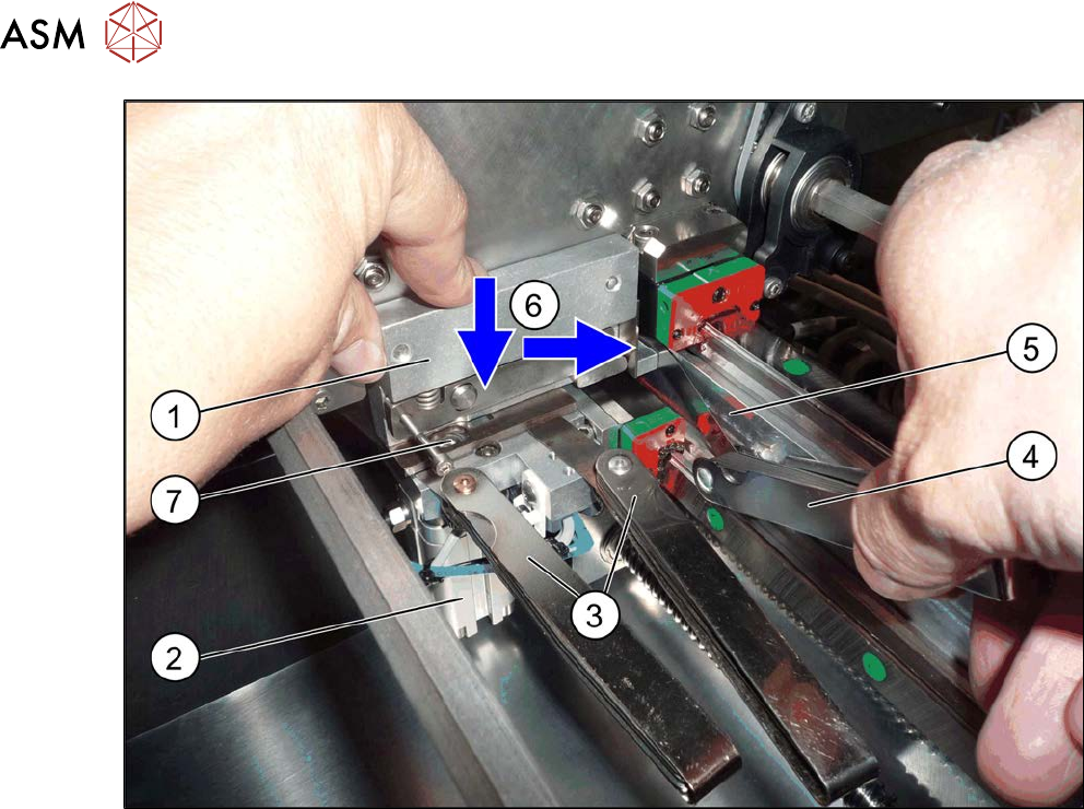
Fig.307: Fitting the clamp
► Place a 0.3 mm feeler gauge (3) between the clamp (1) and cylinder unit (2).
Two feeler gauges are used in the diagram for more clarity.
The feeler gauge should not lie over the parallel pin(7).
► Place a 0.15 mm(4) feeler gauge between the clamps and the clamping surface(5).
► (6) Press the clamps at the same time towards the cylinder unit and towards the clamping sur-
face and then tighten the clamps with a torque of 8Nm.
► Check the distance under the clamps with a 0.25 and 0.3mm feeler gauge. The 0.25 mm
feeler gauge should just have enough room while the 0.3 mm one should not have room to
move.
► Check the distance between the clamps and the clamping surface with a 0.1 and 0.15mm
feeler gauge. The 0.1 mm feeler gauge should just have enough room while the 0.15 mm one
should not have room to move.
► Follow the removal instructions in reverse order for further installation. Also observe the fol-
lowing instructions:
– Check the input/output functions in the software to make sure that the adjustment units
with all sensors are recognized for all conveyor sides.
– Perform calibration of the fixed conveyor sides on the left and right. If you do not, not all
conveyor sides will be calibrated (see7.10.3 "Calibrating the Conveyor Rails" [}301]).
This calibration is needed to ensure that the conveyor sides are positioned correctly.
7 Conveyor
7.5 Width Adjustment, Clamps and Cylinder Unit
Service Manual SIPLACE X-Serie S 06/2019 241
Troubleshooting
NOTICE
Insufficient clamping power
If the conveyor side clamps are no longer clamping enough, this could be because the con-
veyor side has been moved without the brakes (clamps) being released. In this case, pro-
ceed as follows:
► Remove the clamping unit and check its friction surface. If this is no longer rough,
clean the surface with "universal sanding cleaner". Carefully remove any aluminum
shavings on the friction surface.
► Readjust the clamps as described above and then tighten the screws with a torque of
8 Nm.
► If you are unable to set the parallelism of the conveyor sides with the width adjust-
ment, inform your SIPLACE service team.