00197042-04_SM_X-Serie-S_Customer_EN.pdf - 第248页
7 Conveyor 7.6 Conveyor Belt, Belt Drive and Hexagonal Shaft 248 Service Manual SIPLACE X-Serie S 06/2019 Overview of measuring points and values Fig.317: Overview of measuring points and values Side panel Side A Side B…

7 Conveyor
7.6 Conveyor Belt, Belt Drive and Hexagonal Shaft
Service Manual SIPLACE X-Serie S 06/2019 247
Installation
► Follow the removal instructions in reverse order for installation. Also observe the following
instructions:
●
Check the new toothed belt before fitting it. Hold it up high. It should hang loose and should
not twist.
●
Make sure that you do not fold or otherwise damage the toothed belt.
●
Make sure that the toothed belt is positioned accurately in the guidance on the motor shaft or
in the belt drive.
●
If you have loosened the spring, check the bushing for correct orientation when you fit it back
again.
7.7.1 "Replacing the Clamping Plate, Spacer Disks and Tension Spring" [}255]
●
When you tighten the movable roller, set the tension of the toothed belt correctly.
7.6.2 "Setting the belt tension (conveyor belt)" [}247]
7.6.2 Setting the belt tension (conveyor belt)
The precalculated values for setting the belt tension can be found in the following chapters.
In addition, the value for any section of the conveyor belt can be calculated using a formula (see
7.6.2.2 "Calculating the belt tension" [}249]).
7.6.2.1 Setting the Tension of the Conveyor Toothed Belt
Parts, equipment and tools
●
Belt tension device [00326015-xx]
●
With installed input/output extension option:
Assembly instructions "SIPLACE X-Series S Extension Input and Output Con-
veyor" [DEEN:00197089‑xx]
7 Conveyor
7.6 Conveyor Belt, Belt Drive and Hexagonal Shaft
248 Service Manual SIPLACE X-Serie S 06/2019
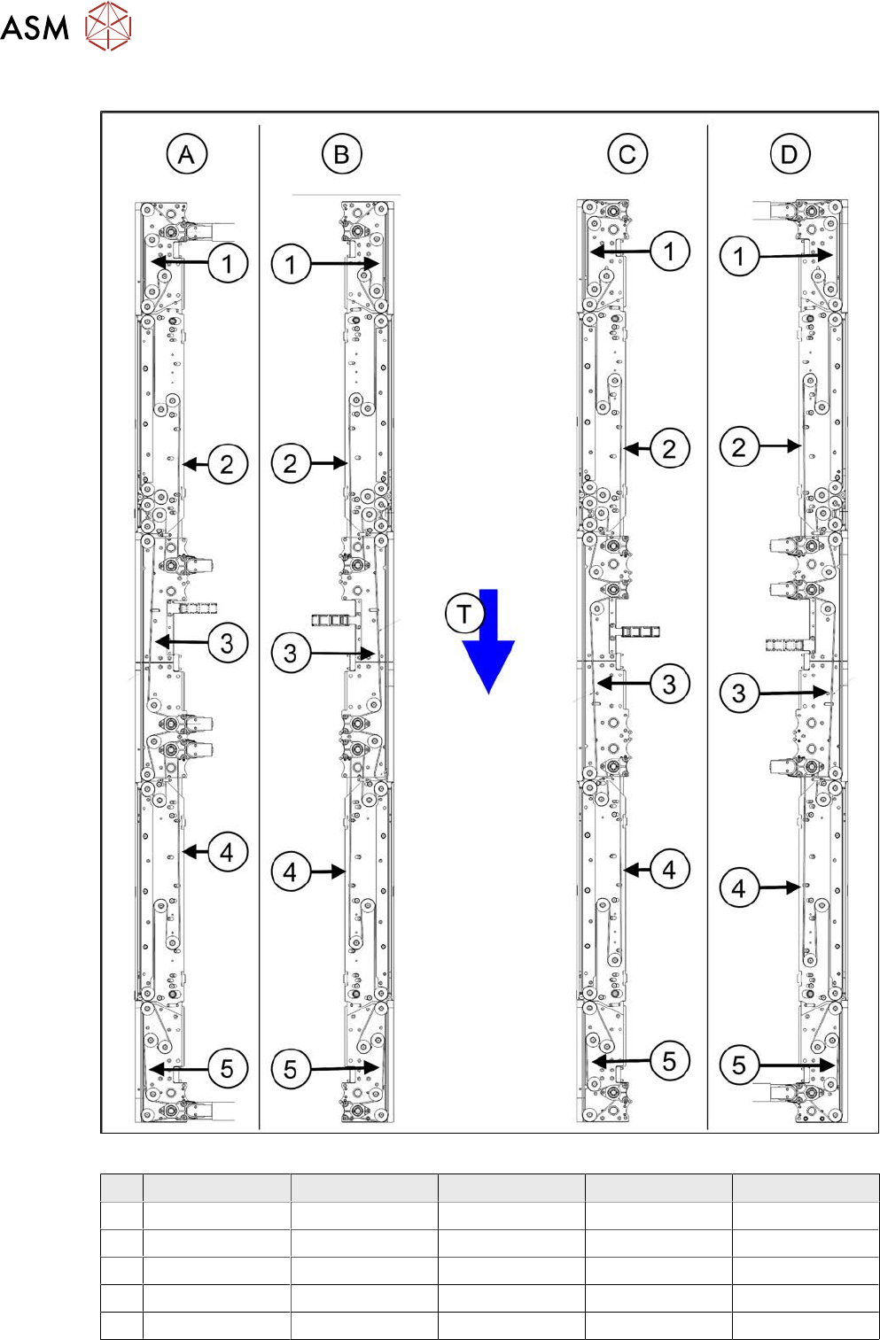
Overview of measuring points and values
Fig.317: Overview of measuring points and values
Side panel Side A Side B Side C Side D
1 Input area 182 +/- 18 182 +/- 18 142 +/- 14 142 +/- 14
2 PA1 49 +/- 5 49 +/- 5 49 +/- 5 49 +/- 5
3 Center 58 +/- 6 58 +/- 6 58 +/- 6 58 +/- 6
4 PA2 49 +/- 5 49 +/- 5 49 +/- 5 49 +/- 5
5 Output area 174 +/- 17 174 +/- 17 211 +/- 21 211 +/- 21
7 Conveyor
7.6 Conveyor Belt, Belt Drive and Hexagonal Shaft
Service Manual SIPLACE X-Serie S 06/2019 249
Setting
► Use the software to move the conveyor sides into a position which allows you best access. As
an alternative, you can loosen the clamps for the relevant sides in dual conveyors.
7.2 "Loosening the Conveyor Side Clamps" [}207]
► Switch off the machine, disconnect it from the power supply and secure it to prevent
unauthorized reactivation.
1.2 "Preparatory work..." [}16]
► Check the belt tension at the relevant measuring point.
► If the belt tension is not correct, set it with the help of the movable idler pulley.
► Repeat the measurement 4 times.
7.6.2.2 Calculating the belt tension
NOTICE
For conveyor belt only
This calculation only applies to the conveyor belt.
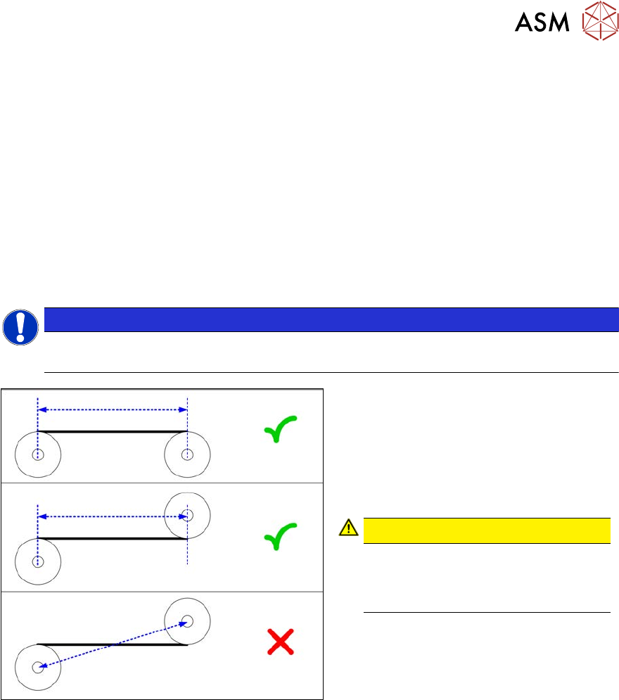
Fig.318: Measuring the distance
► Define the two idler pulleys between
which you want to set the belt tension.
If possible, do not use the movable
idler pulleys.
► Measure the distance between the two
idler pulleys parallel to the conveyor
belt.
CAUTION!
Note that it is not always possible to
simply measure the distance
between the idler pulleys from cen-
ter to center.
.
► Calculate the belt tension using the fol-
lowing formula:
20000 [Hz mm]
/ idler pulley spacing [mm]
The permissible tolerance is always plus/
minus 10% of the calculated value.
Example
Distance between the idler pulleys: 235mm
Calculation:
20000 / 235 = 85 (rounded, exactly 85.106…)
10 % of 85.106… = 9 (rounded, exactly 8.5106…)
Result:
Belt tension: 85 +/-9 Hz