00197042-04_SM_X-Serie-S_Customer_EN.pdf - 第258页
7 Conveyor 7.7 Clamping Plate, Clamping Rails and Belt Guidance 258 Service Manual SIPLACE X-Serie S 06/2019 7.7.2 Replacing the actuator Parts, equipment and tools Fig.326: Actuator (example of SX1/SX2 shown) 1. Actuat…
7 Conveyor
7.7 Clamping Plate, Clamping Rails and Belt Guidance
Service Manual SIPLACE X-Serie S 06/2019 257
Installation
► Transfer the eight markings to the other side of the clamping plate.
► Insert the three top fastening screws into the clamping plate.
► Insert one spacer disk each onto the three fastening screws on the inside of the clamping
plate. Make sure that the coated (dark) side of the spacer disks points to the clamping plate.
► Fit one spacer disk and a little Unisilikon to each of the five lower fastening screws. Make sure
that the coated side of the spacer disks points to the clamping plate.
► Lift the plate with the spacer disks carefully onto the conveyor side.
► First tighten the five bottom screws a little, then the three top screws. Carefully tighten all
screws hand-tight. Do not overtighten the screws, as this could destroy the thread in the side
panels of the conveyor.
CAUTION
Do not tighten the screws excessively!
The thread in the side panels of the conveyor sides are very short and therefore very sens-
itive.
► Make sure that the screws are not tightened excessively! If they are, this could lead to
irreparable damage to the conveyor sides.
NOTICE
Spacer disks
► Make sure that all spacer disks are correctly positioned.
► Before assembly of the springs, check the clamping plate for ease of movement. To
do this, lift the clamping plate and then let it go. It must fall down alone from its own
weight.
Fig.325: Bushing
1. Bushing
2. Screw
► Fit the springs.
CAUTION!
Check the bushing for correct orienta-
tion. The thicker part of the bushing
must be on the side of the conveyor
side.
.
► Thread the conveyor belt back into place. Now set the conveyor belt tension.
7.6.2 "Setting the belt tension (conveyor belt)" [}247]
► Follow the removal instructions in reverse order for further installation.
7 Conveyor
7.7 Clamping Plate, Clamping Rails and Belt Guidance
258 Service Manual SIPLACE X-Serie S 06/2019
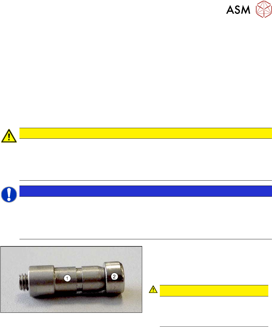
7.7.2 Replacing the actuator
Parts, equipment and tools
Fig.326: Actuator (example of SX1/SX2 shown)
1. Actuator SXa [03092995-xx]
(2x per clamping plate)
Removal
► Use the software to move the conveyor sides into a position which allows you best access. As
an alternative, you can loosen the clamps for the relevant sides in dual conveyors.
7.2 "Loosening the Conveyor Side Clamps" [}207]
► Switch off the machine, disconnect it from the power supply and secure it to prevent
unauthorized reactivation.
1.2 "Preparatory work..." [}16]
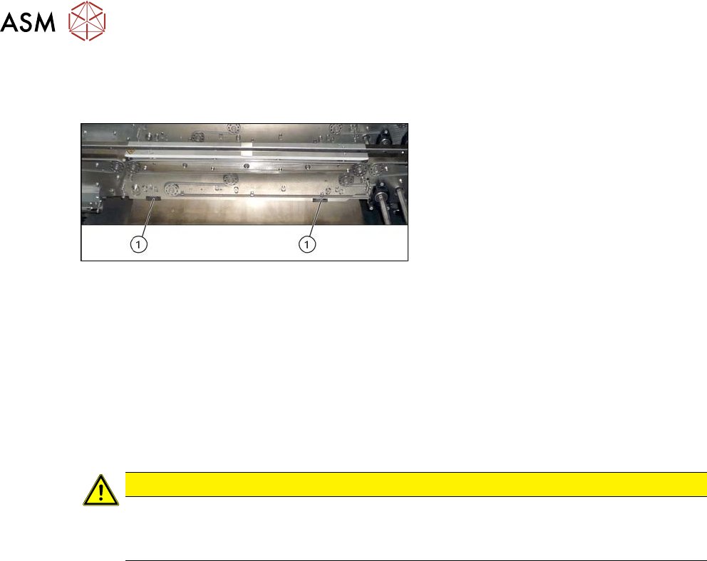
► Pull the actuator off the clamping plate.
CAUTION
Actuator
You may need to lever the actuator off the clamping plate with a screwdriver.
► Take care not to distort the clamping plate.
Installation
► Follow the removal instructions in reverse order for installation. Also observe the following
instructions:
– Carefully push the actuator from below onto the clamping plate, until it engages.
7 Conveyor
7.7 Clamping Plate, Clamping Rails and Belt Guidance
Service Manual SIPLACE X-Serie S 06/2019 259
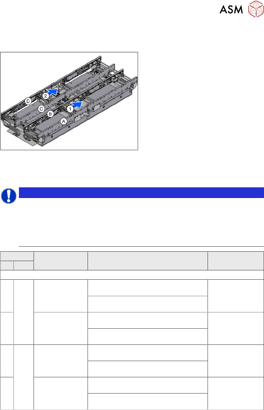
7.7.3 Replacing the Clamping Rail/Belt Guidance
Parts, equipment and tools
Fig.327: Overview of conveyor sides and lanes
1, 2 = Conveyor lane 1 and 2
A to D = conveyor side A to D
The single conveyor only has sides A and B.
Select the required belt guide or clamping rail:
(DC = dual conveyor, SC = single conveyor, PA1/PA2 = placement area 1/2)
NOTICE
Single conveyor
In the case of "single conveyor right", sides A and B of the dual conveyor are used.
In the case of "single conveyor left", sides C and D of the dual conveyor are used.
It is not possible to convert the single conveyor from right to left or vice versa. In this case,
you need to change the conveyor itself. You may wish to contact your SIPLACE service
team regarding this work.
Side panel Input area PA1 Center PA1
DC SC
SIPLACE X4 S, X3 S
A Fixed,
right
[03093894-xx] Belt
guidance A/C PA1
IC SX4a
[03094127-xx] Clamping rail A/C PA1 380
450 assembly SX4a
[03093880-xx] Belt
guidance A/C PA1
OC SX4a
Thick board: [03100557-xx] clamping rail
TBO A/C PA1 380 450 assembly SX4a
B [03094528-xx] Belt
guidance B/D PA1
IC SX4a
[03097848-xx] Clamping rail B/D PA1 450
assembly SX4a
[03094526-xx] Belt
guidance B/D PA1
OC SX4a
Thick board: [03100574-xx] clamping rail
TBO B/D PA1 450 assembly SX4a
C Fixed,
left
[03093894-xx] Belt
guidance A/C PA1
IC SX4a
[03094127-xx] Clamping rail A/C PA1 380
450 assembly SX4a
[03093880-xx] Belt
guidance A/C PA1
OC SX4a
Thick board: [03100557-xx] clamping rail
TBO A/C PA1 380 450 assembly SX4a
D [03094528-xx] Belt
guidance B/D PA1
IC SX4a
[03097848-xx] Clamping rail B/D PA1 450
assembly SX4a
[03094526-xx] Belt
guidance B/D PA1
OC SX4a
Thick board: [03100574-xx] clamping rail
TBO B/D PA1 450 assembly SX4a