00197042-04_SM_X-Serie-S_Customer_EN.pdf - 第264页
7 Conveyor 7.8 Laser light barriers, fiber optic cable and PCB sensors 264 Service Manual SIPLACE X-Serie S 06/2019 Overview Fig.330: Overview of laser light barriers A to D Conveyor side A to D 1, 2 Conveyor lane 1, co…

7 Conveyor
7.8 Laser light barriers, fiber optic cable and PCB sensors
Service Manual SIPLACE X-Serie S 06/2019 263
7.8 Laser light barriers, fiber optic cable and PCB sensors
7.8.1 Replacing the Laser Light Barrier for the Transmitter/Receiver
Parts, equipment and tools
NOTICE
Old and new version of transmitter and receiver
There are old and new versions of the transmitter and receiver modules.
Old: [03092578-xx], [03091492-xx]
New: [03109439‑xx] (contains: 03098280-xx, 03098281-xx)
► The old version can be replaced with the new one.
► The transmitter and receiver of the new version are coordinated with one an-
other and must always be replaced together. It is not possible to just replace the
transmitter or receiver alone.
► In the old version, the connection cable is fixed to the module.
In the new version, the connection cable has a plug at each end. In this case, the con-
nection cable needs to be connected to the module before it is fitted.
●
Light barrier transmitter and receiver SX1V2 / X‑SeriesS [03109439‑xx] (replaces:
03092578‑xx, 03091492‑xx)
●
Flashlight, if needed
●
Magnet lifter, if needed
●
Tweezers, if needed
●
If needed, semi-transparent paper or plastic (for better recognition of the laser beam)
7 Conveyor
7.8 Laser light barriers, fiber optic cable and PCB sensors
264 Service Manual SIPLACE X-Serie S 06/2019
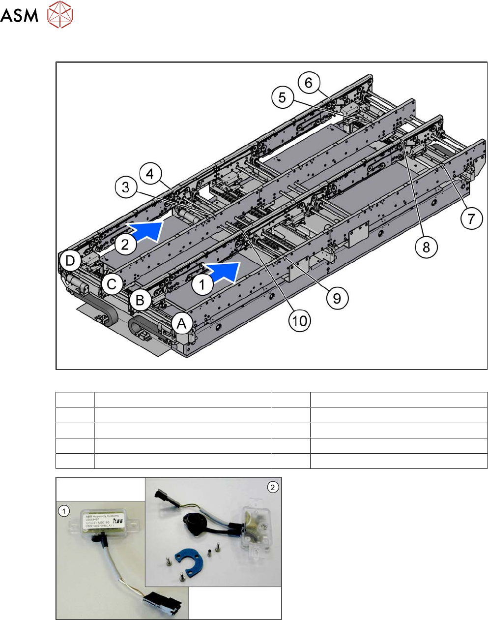
Overview
Fig.330: Overview of laser light barriers
A to D Conveyor side A to D 1, 2 Conveyor lane 1, conveyor lane 2
3 Transmitter PA1 side C 4 Receiver PA1 side D
5 Transmitter PA2 side C 6 Receiver PA2 side D
7 Transmitter PA2 side A 8 Receiver PA2 side B
9 Transmitter PA1 side A 10 Receiver PA1 side B
Fig.331: Overview of transmitter and receiver (old version)
1. Receiver
2. Transmitter (incl. assembly material)
7 Conveyor
7.8 Laser light barriers, fiber optic cable and PCB sensors
Service Manual SIPLACE X-Serie S 06/2019 265
Removal
CAUTION
Move the conveyor sides carefully!
The clamping and guide rails are a key stabilizing element for the conveyor side, which is
then less stable once they have been removed.
► Move the opened conveyor sides very carefully.
► Make sure that the sides are always pushed equally on the left and right.
► Make sure that you do not distort the sides.
► Switch off the machine, disconnect it from the power supply and secure it to prevent
unauthorized reactivation.
1.2 "Preparatory work..." [}16]
► Dismantle the two clamping rails/belt guides on the transmitter/receiver.
7.7.3 "Replacing the Clamping Rail/Belt Guidance" [}259]
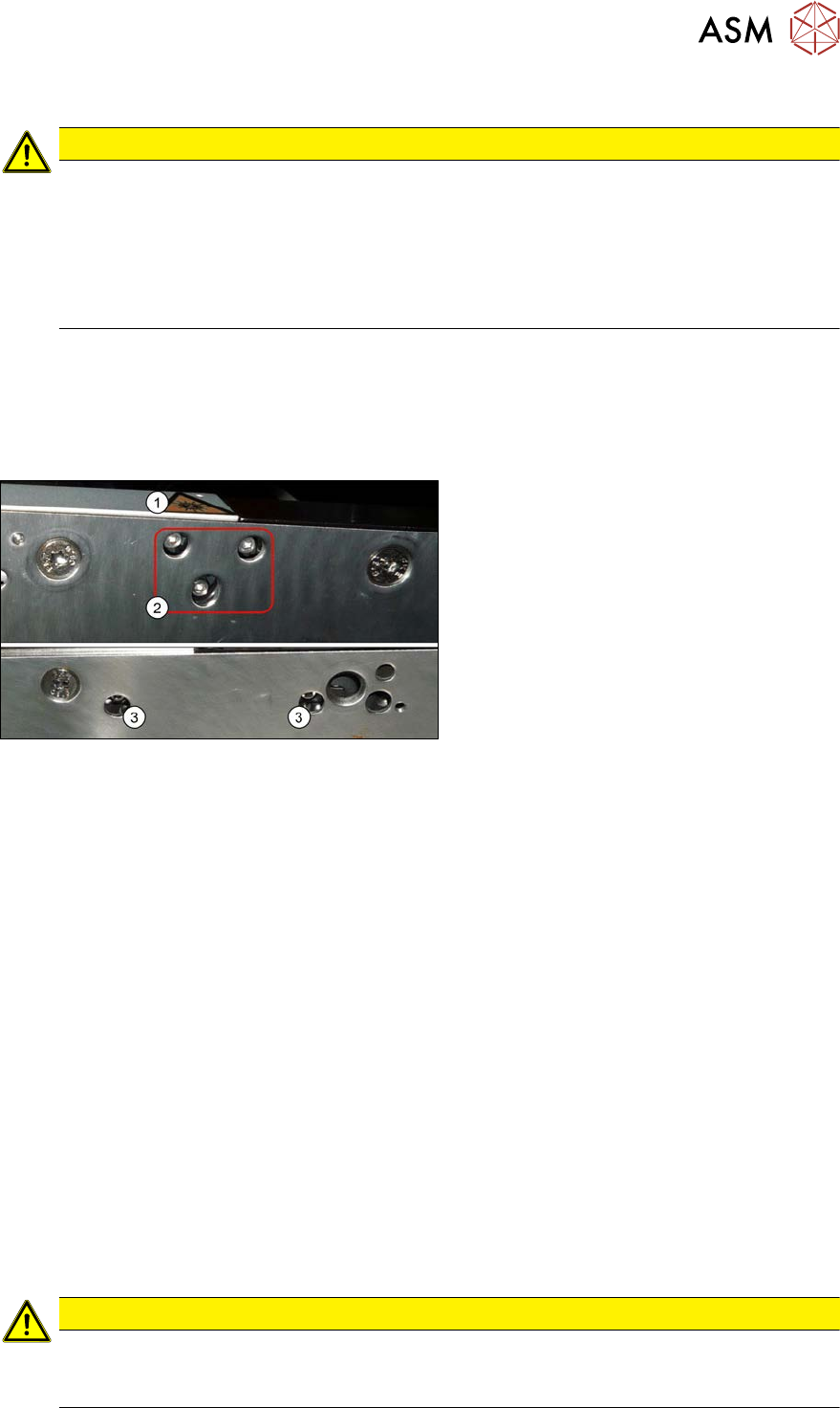
Fig.332: Fastening screws
The transmitters are always near the laser
warning labels(1). The receivers are always
on the opposite side walls.
► Transmitter: Remove the three fasten-
ing screws(2). Make sure that no parts
fall into the conveyor side wall.
► Receiver: Remove the two fastening
screws (3). Make sure that no parts fall
into the conveyor side wall.
► Unplug the electrical connection.
Installation
► Follow the removal instructions in reverse order for installation. Also observe the following
instructions:
●
Reconnect the transmitter/receiver before installation.
●
Make sure that all the other cables in the conveyor side are run under the transmitter/recei-
ver. There is a particular lack of space at the transmitters.
If needed, the screw behind the housing can be loosened and replaced with a shorter screw
(8mm).
The screws could also be in the way of the idler pulleys.
See the following diagrams for details.
●
Use the bushing for the bottom screw. This screw is used to fix the sensor.
The two upper screws are used to adjust the laser beam.
●
The transmitters are fixed hand-tight with the lower screw and adjusted with the top two
screws.
●
Check the setting for the transmitter/receiver and correct if necessary.
7.8.3 "Checking the laser light barrier" [}270]
7.8.4 "Correcting the Laser Light Barrier Setting" [}273]
●
Teach the PCB sensors using the station software (see 7.8.9 "Teaching the PCB sensors
(SW70x)" [}288]).
CAUTION
Do not dismantle the cover plate!
The cover plate has been hidden for greater clarity in the following diagrams. Do not dis-
mantle this!