00197042-04_SM_X-Serie-S_Customer_EN.pdf - 第270页
7 Conveyor 7.8 Laser light barriers, fiber optic cable and PCB sensors 270 Service Manual SIPLACE X-Serie S 06/2019 Fig.341: Connections (here output conveyor location 3) ► Disconnect the cable. You may want to mark the…
7 Conveyor
7.8 Laser light barriers, fiber optic cable and PCB sensors
Service Manual SIPLACE X-Serie S 06/2019 269
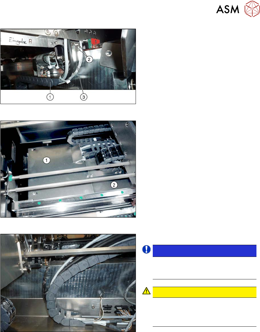
Fig.338: Holding plate
► Remove the screws(2) fastening the
bracket(3) to the top end of the trailing
cable(1) on the conveyor side.
► For better access, you can remove the
screws fastening the trailing cable to
the bracket.
Fig.339: Cover plates (example of SX1/SX2 shown)
► In the intermediate conveyor: dismantle
the two cover plates(1) and (2) under
the trailing cable. To do this, loosen the
four fastening screws for each and then
remove the cover plates.
Fig.340: Opened trailing cable
► Open the trailing cable.
NOTICE!
There is also a protective tape in the
trailing cable. This separates the fiber
optic cable from the cables.
.
CAUTION!
Make sure you do not bend the fiber
optic cable. These could otherwise be-
come cloudy or break and no longer
transmit the signal properly.
.
► For better access, you can remove the
screws fastening the trailing cable to
the bottom of the conveyor.
► Thread the cable out of the conveyor
side and the trailing cable.
7 Conveyor
7.8 Laser light barriers, fiber optic cable and PCB sensors
270 Service Manual SIPLACE X-Serie S 06/2019
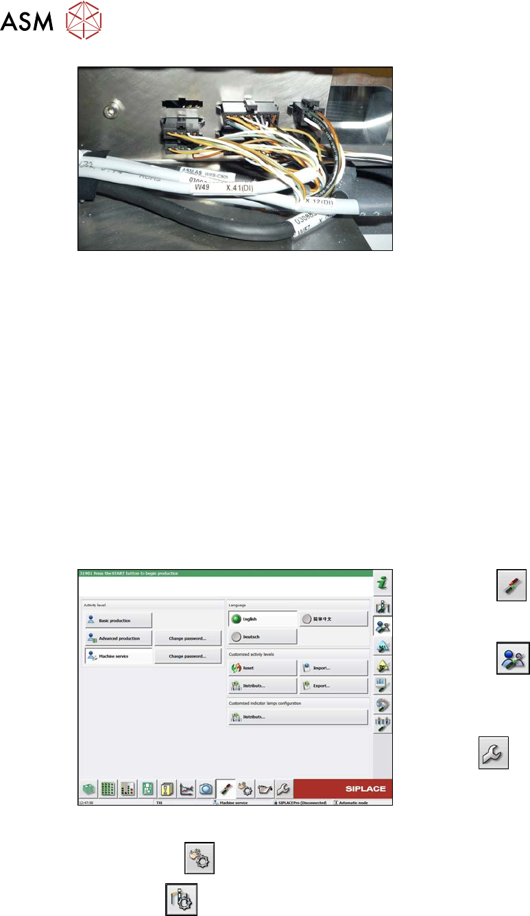
Fig.341: Connections (here output conveyor location 3)
► Disconnect the cable. You may want to
mark the position, to make clear as-
signment easier later on.
Installation
► Follow the removal instructions in reverse order for installation. Also observe the following
instructions:
– Leave enough room at the cable for easy removal of the transmitter/receiver from the side
wall. Make sure that the connector is not directly under the housing, otherwise you might
have problems inserting the module.
– Replace any open cable ties.
Make sure that the cable ties and the heads of the cable ties do not rub against any parts
when you do this.
– Check the setting for the transmitter/receiver and correct if necessary.
– Teach the PCB sensors.
7.8.3 Checking the laser light barrier
Whenever the laser light barrier is dismantled, it then needs to be checked and manually set again,
if necessary. Check the setting as follows:
Fig.342: Select operator level
► Select the
button, to open the
Configure, update and calibrate the
machine menu.
► Select the
button to open the
Check and set user settings menu.
► Switch over to the operator level Ma-
chine service.
ð The
button will be shown.
► Click on the
button, to switch over to the menu Check sensors and functions.
► Click the
button.
7 Conveyor
7.8 Laser light barriers, fiber optic cable and PCB sensors
Service Manual SIPLACE X-Serie S 06/2019 271
Fig.343: Safety mode
► Enable the button Safety mode (re-
duced speed).
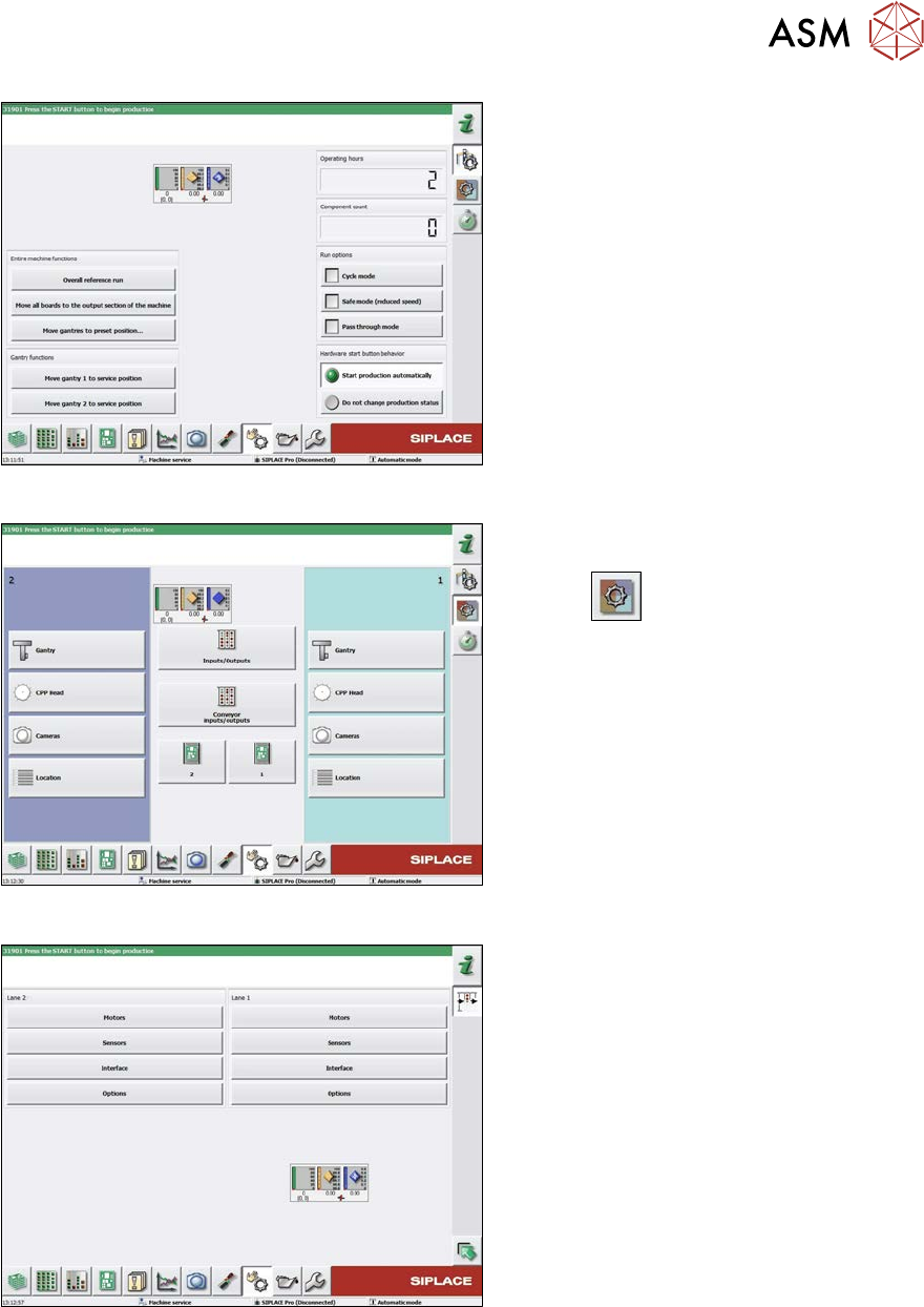
Fig.344: Check sensors and functions
► Click on the button Check sensors
and functions of specific compon-
ents
.
► Click on the Conveyor inputs/outputs
button.
Fig.345: Inputs/outputs
► Click on the button Sensors.