00197042-04_SM_X-Serie-S_Customer_EN.pdf - 第297页
7 Conveyor 7.10 Conveyor sides Service Manual SIPLACE X-Serie S 06/2019 297 7.10.1.3 Conveyor Sides - Settings The following diagram shows a conveyor with the fixed conveyor side on the right. The same set- tings apply t…
7 Conveyor
7.10 Conveyor sides
296 Service Manual SIPLACE X-Serie S 06/2019
Fig.373: Setting the conveyor side
► In the software set the fixed conveyor
side and the position.
NOTICE!
This menu is accessible from operator
level Service (customer)!
.
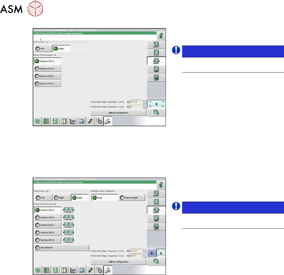
7.10.1.2 Setting the Fixed Conveyor Side on Dual Conveyors
The fixed conveyor edge is always set with the software for dual conveyors.
Setting
Fig.374: Setting the conveyor side position
► In the software set the fixed conveyor
side and the position (see 7.10.1.3
"Conveyor Sides - Settings" [}297]).
NOTICE!
This menu is accessible from operator
level Service (customer)!
.
7 Conveyor
7.10 Conveyor sides
Service Manual SIPLACE X-Serie S 06/2019 297
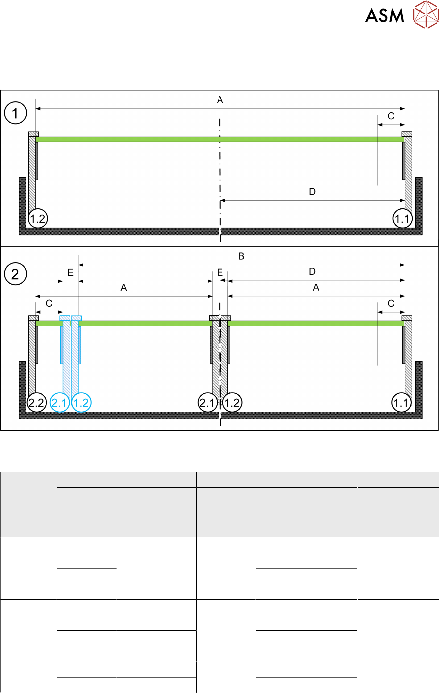
7.10.1.3 Conveyor Sides - Settings
The following diagram shows a conveyor with the fixed conveyor side on the right. The same set-
tings apply to conveyors with the fixed rail on the left.
Fig.375: View of a conveyor with a fixed side on the right (X-Series S as example)
SIPLACE X3 S, X4 S, X4i S
A B C D E
Maximum
PCB width
Dual as single
conveyor
(flex)
Minimum
PCB width
Position of fixed
conveyor side
(from the
conveyor center)
Minimum
side distance
side 1.2/2.1
Single con-
veyor
460 --- 50 mm 231 ---
560 256
560 281
685 344
Dual con-
veyor
216 413 50 mm 234.2 35 mm
236 433 254 36 mm
250 450 268
260 460 281 35 mm
300 510 320
320 560 344
7 Conveyor
7.10 Conveyor sides
298 Service Manual SIPLACE X-Serie S 06/2019
7.10.2 Setting the Parallelism of the Conveyor Sides and Adjustment Units
7.10.2.1 Setting the Parallelism of the Adjustment Unit
Setting
► This setting is identical for the dual conveyor. For more information about this, read section
7.10.2.2 "Setting the parallelism of the conveyor side walls and adjustment units for dual con-
veyors" [}298].
NOTICE
Procedure identical to that for adjustment units on dual conveyor
In a single conveyor, the movable conveyor side is directly connected with the recirculating
ball screws of the width adjustment. This is set via the toothed belt. This must jump one or
more teeth via the relevant idler pulleys.
7.10.2.2 Setting the parallelism of the conveyor side walls and adjustment units for dual
conveyors
NOTICE
Adjustment units
The parallelism of the conveyor sides depends on the parallelism of the adjustment units.
This is set via the toothed belt. This must jump one or more teeth via the relevant idler pul-
leys.
► If you unable to set the parallelism, contact your local SIPLACE Service team.
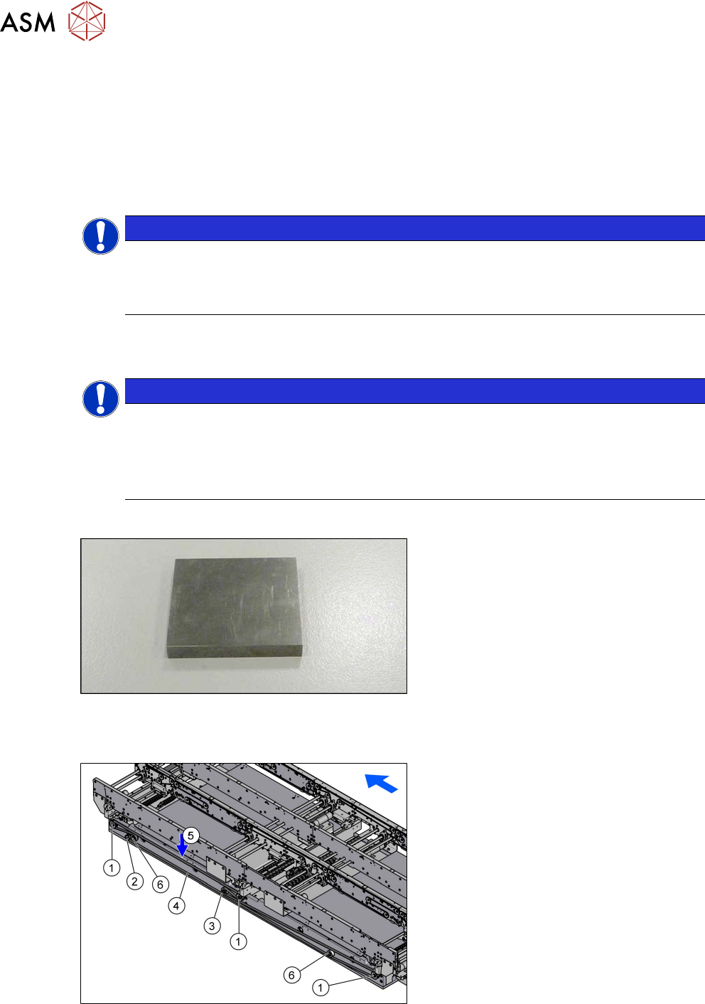
Parts, equipment and tools
Fig.376: Metal pieces
●
To check the adjustment unit stoppers,
you need two suitably sized and
identical pieces of metal (see below).
You could also use two lifting table
plate guides if needed.
Overview
Fig.377: Overview width adjustment
1. Adjustment units
2. Width adjustment drive
3. Movable idler pulley
4. Toothed belt of width adjustment
5. Measurement point for belt tension
6. Idler pulley