00197042-04_SM_X-Serie-S_Customer_EN.pdf - 第298页
7 Conveyor 7.10 Conveyor sides 298 Service Manual SIPLACE X-Serie S 06/2019 7.10.2 Setting the Parallelism of the Conveyor Sides and Adjustment Units 7.10.2.1 Setting the Parallelism of the Adjustment Unit Setting ► This…
7 Conveyor
7.10 Conveyor sides
Service Manual SIPLACE X-Serie S 06/2019 297
7.10.1.3 Conveyor Sides - Settings
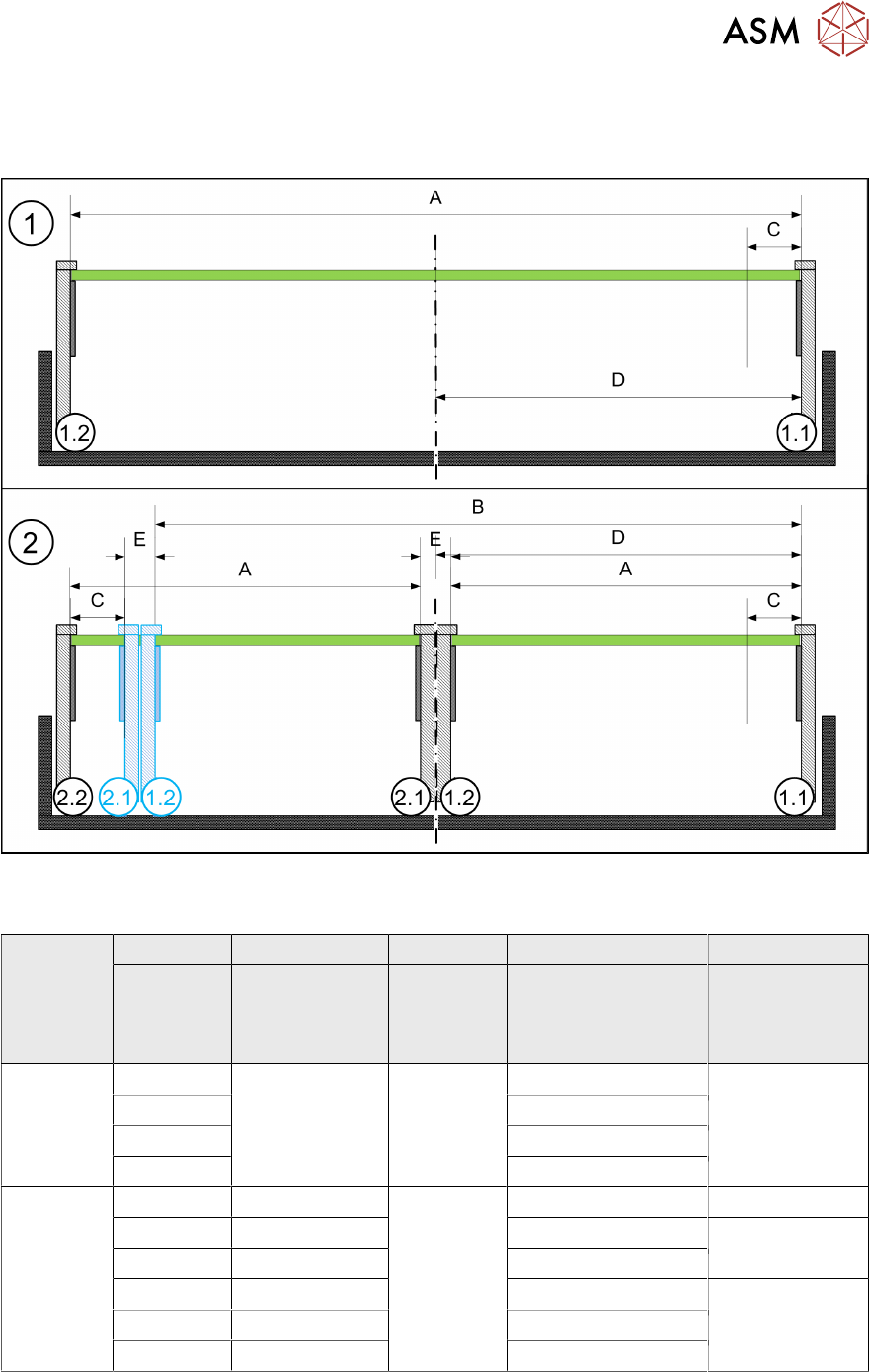
The following diagram shows a conveyor with the fixed conveyor side on the right. The same set-
tings apply to conveyors with the fixed rail on the left.
Fig.375: View of a conveyor with a fixed side on the right (X-Series S as example)
SIPLACE X3 S, X4 S, X4i S
A B C D E
Maximum
PCB width
Dual as single
conveyor
(flex)
Minimum
PCB width
Position of fixed
conveyor side
(from the
conveyor center)
Minimum
side distance
side 1.2/2.1
Single con-
veyor
460 --- 50 mm 231 ---
560 256
560 281
685 344
Dual con-
veyor
216 413 50 mm 234.2 35 mm
236 433 254 36 mm
250 450 268
260 460 281 35 mm
300 510 320
320 560 344
7 Conveyor
7.10 Conveyor sides
298 Service Manual SIPLACE X-Serie S 06/2019
7.10.2 Setting the Parallelism of the Conveyor Sides and Adjustment Units
7.10.2.1 Setting the Parallelism of the Adjustment Unit
Setting
► This setting is identical for the dual conveyor. For more information about this, read section
7.10.2.2 "Setting the parallelism of the conveyor side walls and adjustment units for dual con-
veyors" [}298].
NOTICE
Procedure identical to that for adjustment units on dual conveyor
In a single conveyor, the movable conveyor side is directly connected with the recirculating
ball screws of the width adjustment. This is set via the toothed belt. This must jump one or
more teeth via the relevant idler pulleys.
7.10.2.2 Setting the parallelism of the conveyor side walls and adjustment units for dual
conveyors
NOTICE
Adjustment units
The parallelism of the conveyor sides depends on the parallelism of the adjustment units.
This is set via the toothed belt. This must jump one or more teeth via the relevant idler pul-
leys.
► If you unable to set the parallelism, contact your local SIPLACE Service team.
Parts, equipment and tools
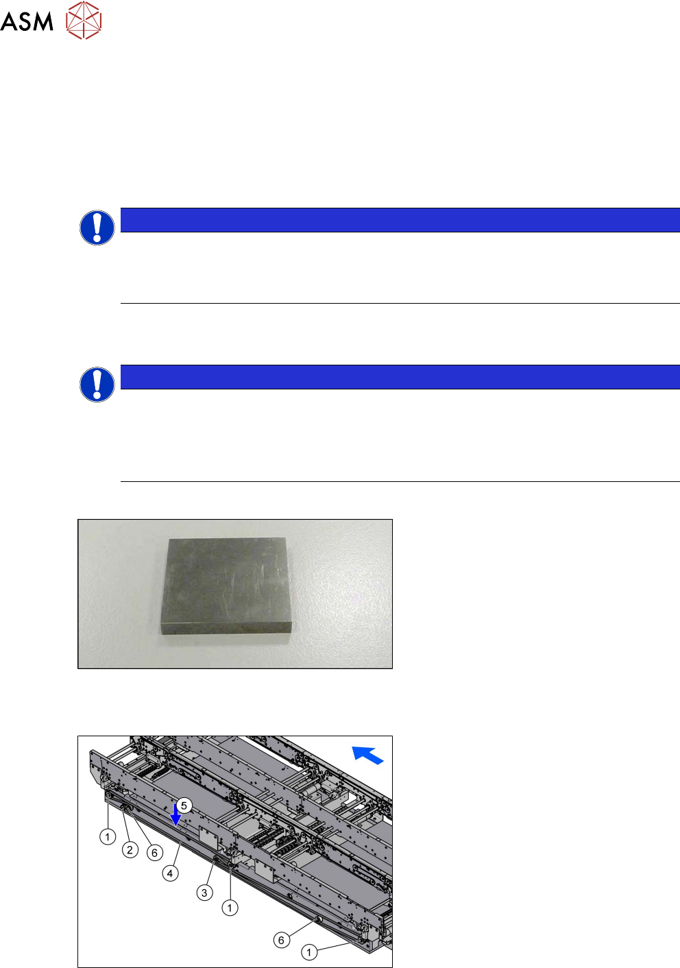
Fig.376: Metal pieces
●
To check the adjustment unit stoppers,
you need two suitably sized and
identical pieces of metal (see below).
You could also use two lifting table
plate guides if needed.
Overview
Fig.377: Overview width adjustment
1. Adjustment units
2. Width adjustment drive
3. Movable idler pulley
4. Toothed belt of width adjustment
5. Measurement point for belt tension
6. Idler pulley
7 Conveyor
7.10 Conveyor sides
Service Manual SIPLACE X-Serie S 06/2019 299
Setting
► Use the software to move the conveyor sides into a position which allows you best access. As
an alternative, you can loosen the clamps for the relevant sides in dual conveyors.
7.2 "Loosening the Conveyor Side Clamps" [}207]
► Switch off the machine, disconnect it from the power supply and secure it to prevent
unauthorized reactivation.
1.2 "Preparatory work..." [}16]
► Dismantle the lifting table plate at location 3 and 4.
7.3.1 "Replacing the lifting table plate" [}212]
► Loosen the movable idler pulley for the toothed belt (width adjustment). The toothed belt of
the width adjustment should then have enough play so that you can move the adjustment
units independently of one another. You may need to remove the toothed belt from the idler
pulleys.
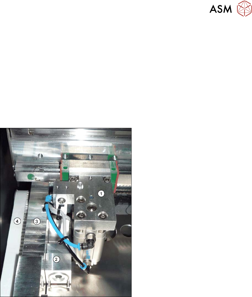
Fig.378: Adjustment unit (example of SX1/SX2 shown)
1. Adjustment unit
2. Spacer piece (here:lifting table fixture)
3. Frame
4. Toothed belt of width adjustment
► Place the toothed belt over the two up-
per idler pulleys so that the adjustment
units move exactly parallel to one an-
other. Check the parallelism as follows:
► Push the adjustment units by hand out-
wards, to one side of the conveyor. In-
sert a spacer piece in each case. This
helps you to check the distance to the
frame more easily. Make sure that the
lifting table plate guides are only lying
against the adjustment unit base struc-
tures and not against the threads.