00197042-04_SM_X-Serie-S_Customer_EN.pdf - 第30页
2 Basic Machine 2.3 Guide Rollers on the Covers 30 Service Manual SIPLACE X-Serie S 06/2019 Procedure ► To make the work easier, proceed as follows: Dismantle the bottom stop. ► Loosen the screwed fixture on the roller (…
2 Basic Machine
2.3 Guide Rollers on the Covers
Service Manual SIPLACE X-Serie S 06/2019 29
2.3 Guide Rollers on the Covers
NOTICE
Example shown as diagram
The following sections are described using the example of an SX1/SX2 machine. The pro-
cedure is the same for other machines. Any relevant differences will be mentioned expli-
citly.
Parts, equipment and tools
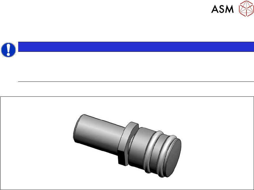
Fig.14: Guide roller [03078561-xx]
●
Per machine:
– 8x roller assy – 1 unit [03078561-xx]
– 8x DIN EN ISO 4028 M8x16-A2-21H – pack of 10 [03027433‑xx] (replaces[00304354‑xx])
or
8x DIN EN ISO4026-M8x16-A2-21H - pack of 10 [03025582-xx]
●
Fork wrench, size 10
●
Allen key
2 Basic Machine
2.3 Guide Rollers on the Covers
30 Service Manual SIPLACE X-Serie S 06/2019
Procedure
► To make the work easier, proceed as follows:
Dismantle the bottom stop.
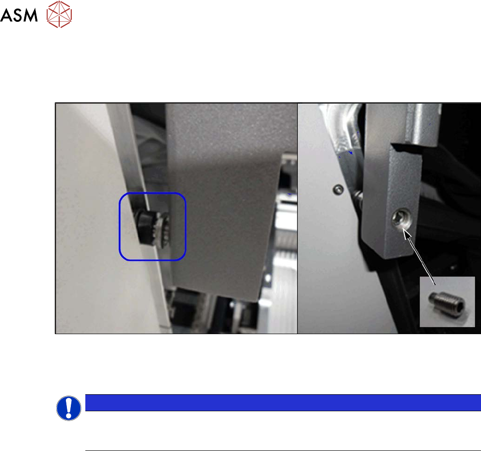
► Loosen the screwed fixture on the roller (fork wrench size10). Unscrew as far as required.
Fig.15: Threaded pin
► From the inside, screw on a threaded pin as lock and tighten it.
Checks
NOTICE
Covering
Between the roller and the guidance there must be at least 75% coverage along the entire
length of the guide rails.
► Check whether the cover can be easily moved along the whole area. Adjust the cover if ne-
cessary (see 2.4 "Setting the Covers" [}31]).
2 Basic Machine
2.4 Setting the Covers
Service Manual SIPLACE X-Serie S 06/2019 31
2.4 Setting the Covers
2.4.1 Overview
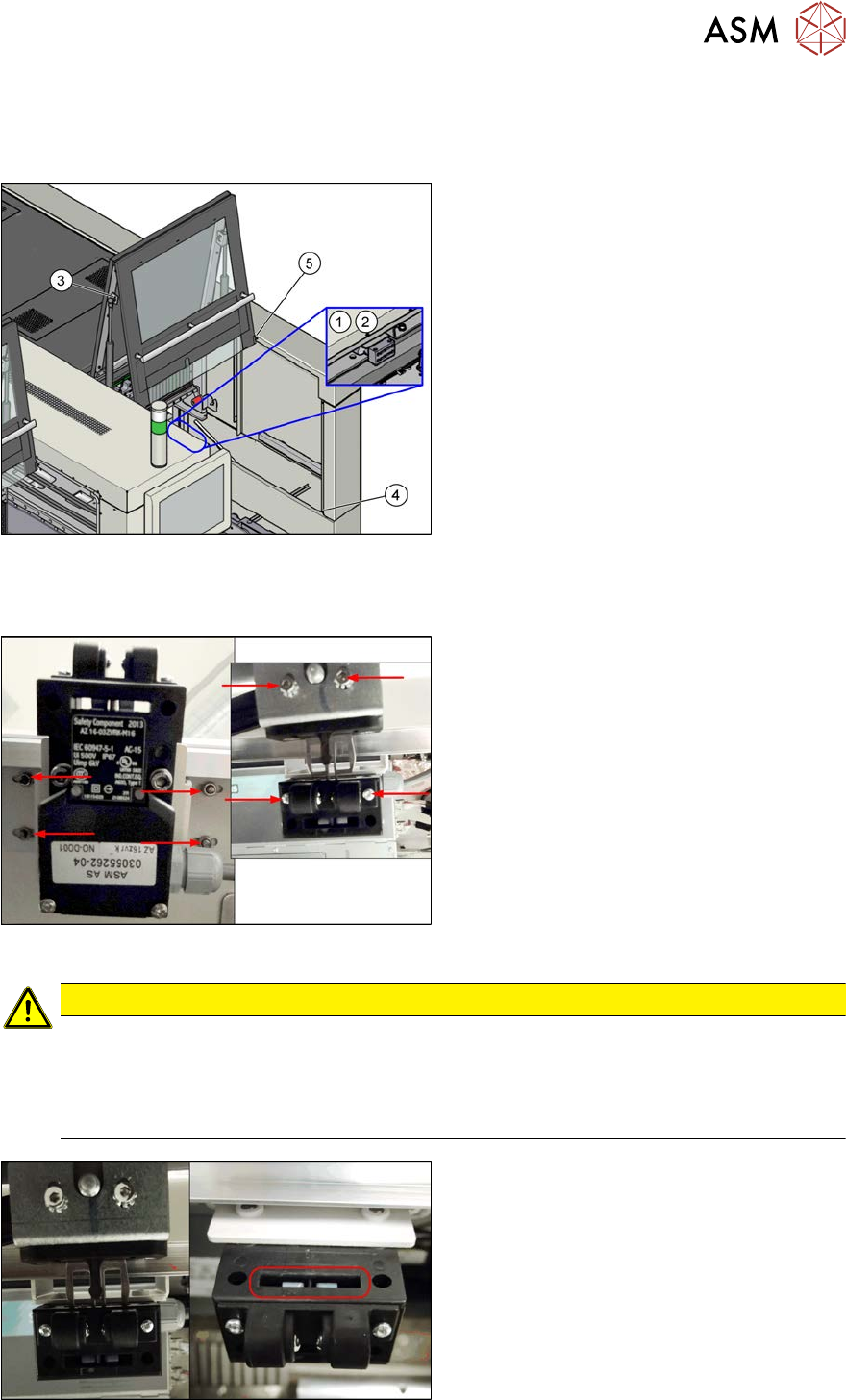
Fig.16: Overview of Settings
1. Setting the cover switch
See 2.4.2 "Setting the Cover
Switch" [}31]
2. Setting the cover switch centering
See 2.4.3 "Setting the Cover Switch
Centering Device" [}32]
3. Setting the actuator
See 2.4.4 "Setting the Actuator" [}32]
4. Setting the bottom stop
See 2.4.5 "Setting the Bottom
Stop" [}33]
5. Setting the rollers
See 2.4.6 "Setting the Cover
Rollers" [}34]
2.4.2 Setting the Cover Switch
Fig.17: Cover switch (example of SIPLACE SX2 shown)
Cover switch [03055262-xx]
► Loosen the screws fastening the cover
switch, the centering device and the ac-
tuator, so that the assemblies can be
easily moved.
CAUTION
Screws on actuator
With enforcement of the Machinery Directive DIN EN 1088 (2009), the following has been
executed to avoid misuse (e.g. putting the safety features out of action): the actuator and
machine protective switch screws have been replaced by Torx screws with pins. The relev-
ant set of tools may only be used for performing repair work.
Fig.18: Cover switch (example of SIPLACE SX2 shown)
► Close the cover far enough for the actu-
ator to be just over the switch. Align
them so that the metal bracket is parallel
to the opening in the switch. The metal
bracket may not scrape against the
cover switch.
► Tighten the cover switch screws in this
position.