00197042-04_SM_X-Serie-S_Customer_EN.pdf - 第300页
7 Conveyor 7.10 Conveyor sides 300 Service Manual SIPLACE X-Serie S 06/2019 Fig.379: Spacer (example of SX1/SX2 shown) 1 View from the side 2 View from above 3 Spacer piece (here: metal platelet) 4 Adjustment unit 5 Fra…
7 Conveyor
7.10 Conveyor sides
Service Manual SIPLACE X-Serie S 06/2019 299
Setting
► Use the software to move the conveyor sides into a position which allows you best access. As
an alternative, you can loosen the clamps for the relevant sides in dual conveyors.
7.2 "Loosening the Conveyor Side Clamps" [}207]
► Switch off the machine, disconnect it from the power supply and secure it to prevent
unauthorized reactivation.
1.2 "Preparatory work..." [}16]
► Dismantle the lifting table plate at location 3 and 4.
7.3.1 "Replacing the lifting table plate" [}212]
► Loosen the movable idler pulley for the toothed belt (width adjustment). The toothed belt of
the width adjustment should then have enough play so that you can move the adjustment
units independently of one another. You may need to remove the toothed belt from the idler
pulleys.
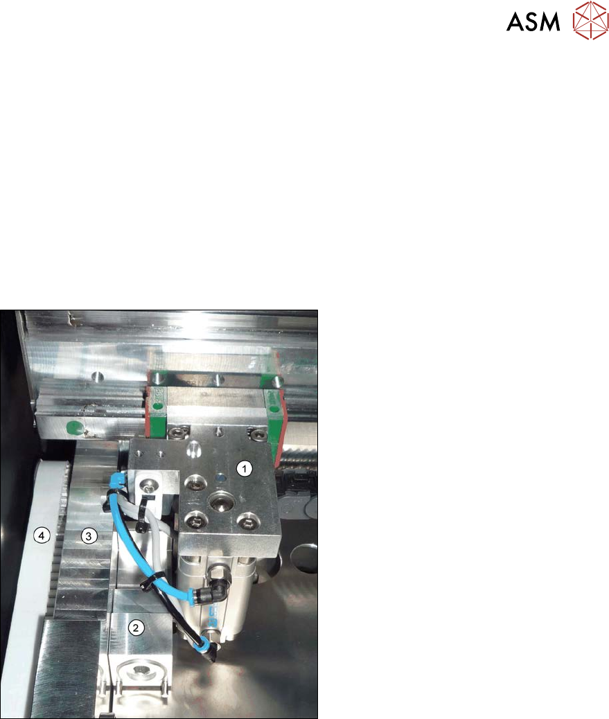
Fig.378: Adjustment unit (example of SX1/SX2 shown)
1. Adjustment unit
2. Spacer piece (here:lifting table fixture)
3. Frame
4. Toothed belt of width adjustment
► Place the toothed belt over the two up-
per idler pulleys so that the adjustment
units move exactly parallel to one an-
other. Check the parallelism as follows:
► Push the adjustment units by hand out-
wards, to one side of the conveyor. In-
sert a spacer piece in each case. This
helps you to check the distance to the
frame more easily. Make sure that the
lifting table plate guides are only lying
against the adjustment unit base struc-
tures and not against the threads.
7 Conveyor
7.10 Conveyor sides
300 Service Manual SIPLACE X-Serie S 06/2019
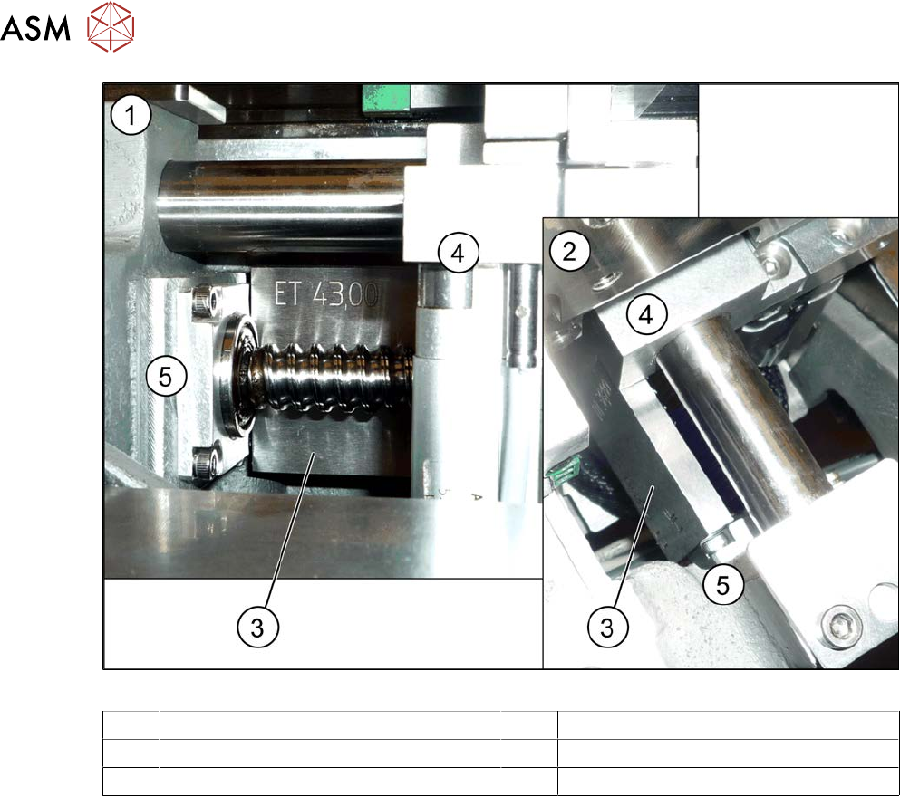
Fig.379: Spacer (example of SX1/SX2 shown)
1 View from the side 2 View from above
3 Spacer piece (here: metal platelet) 4 Adjustment unit
5 Frame 6 Warehouse
► Position the adjustment units so that these lie flush against the lifting table guides between the
frame and the adjustment unit.
► Tighten the fastening screw of the movable idler pulley.
► Check the parallelism of the adjustment units again and correct again if necessary.
► If the conveyor side clamps have loosened, fix these again.
► Set the tension of the toothed belt.
7.5.2.1 "Setting the belt tension (width adjustment)" [}228]
► Calibrate the width adjustment motor.
(The calibration is identical for the lifting table motor.)
► Use the software to move the fixed conveyor side. This ensures that the fixed conveyor side is
parallel to the flexible sides. Readjust the fixed conveyor side to its original value after that.
7 Conveyor
7.10 Conveyor sides
Service Manual SIPLACE X-Serie S 06/2019 301
7.10.3 Calibrating the Conveyor Rails
NOTICE
This chapter is valid for machines with dual conveyor (DC) only.
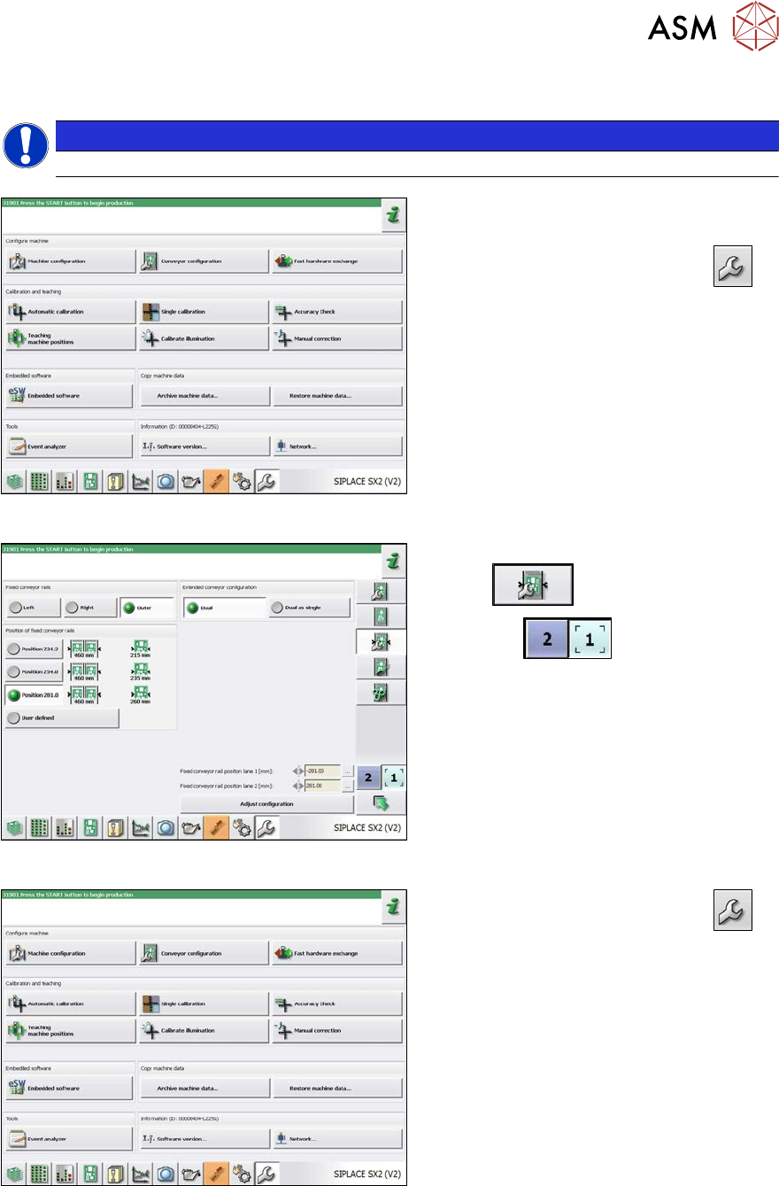
Fig.380: Service menu
► Switch over to the activity level "Ser-
vice (customer)" (or better still).
► Switch over to the service menu
.
► Select "Conveyor configuration".
Fig.381: Setting the conveyor side
► Select "Set options for conveyor fixed
rail"
.
► Use the
button to select the
required conveyor lane.
► Set the conveyor position.
The fixed sides will later have their original
positions again.
Fig.382: Service menu
► Switch over to the service menu
.
► Select "Single calibration".