00197042-04_SM_X-Serie-S_Customer_EN.pdf - 第313页
8 Head exchange 8.5 Replacing the SIPLACE C&P20P/M2 Service Manual SIPLACE X-Serie S 06/2019 313 8.5 Replacing the SIPLACE C&P20P/M2 NOTICE Vacuum test ► If required, perform a vacuum test before removing the p…

8 Head exchange
8.4 SIPLACE C&P20 P on SIPLACE X-Series S machines
312 Service Manual SIPLACE X-Serie S 06/2019
Installation
► Follow the removal instructions in reverse order for installation. Also observe the following
instructions:
– If you replace the head without component camera, you will need to fit the old camera into
the new head. Read the service manual for your placement head for more information.
– In vacuum pump mode, you need to dismantle the silencer from the old head and fit it to
the new one. Refer to the appropriate vacuum pump assembly instructions for details.
– Make sure that the assembly position on the head plate is correct.
– Tighten the four head fastening screws (M4, TX20) with a torque of 2.7 Nm.
NOTICE
Various hose lengths on SIPLACE X-Series S
The hose to the pressure control valve will vary in length, depending on the installation loc-
ation (standard gantry or rotated gantry).
► Shorten or replace the hose, where necessary.
1.2 "Preparatory work..." [}16]
5.2 "Disabling the compressed air supply" [}134]
See also
2 8.8 "Installation Positions on the Head Plate" [}323]
8.4 SIPLACE C&P20 P on SIPLACE X-Series S machines
NOTICE
Vacuum pump/compressed air mode on SIPLACE X-Series S machines
► Compressed air mode: if the SIPLACE C&P20 P is operated without a vacuum
pump, you must convert the head to compressed air mode. You will need the "Conver-
sion kit for compressed air mode SIPLACE C&P20P" [03106765‑xx].
► Vacuum pump mode (default): If the SIPLACE C&P20 P is operated with a vacuum
pump, you will need the "Upgrade kit pressure sensor vacuum C&P20P for SIPLACE
X‑SeriesS" [03108457‑xx].
8 Head exchange
8.5 Replacing the SIPLACE C&P20P/M2
Service Manual SIPLACE X-Serie S 06/2019 313
8.5 Replacing the SIPLACE C&P20P/M2
NOTICE
Vacuum test
► If required, perform a vacuum test before removing the placement head.
Read the "Service manual Vacuum test at C&P placement head" [DE+EN:
00196101‑xx] for this.
NOTICE
Prerequisites for the SIPLACE C&P20P
The following additional conditions must be fulfilled for operating a SIPLACE C&P20P:
► Head interface - at least function state [03091013-03] / [03091023-03]
► Base adapter - minimum function state [03055516-06] / [03045647-08]
► MHCU – at least function state [03090990-03]
► Nozzle changers [03103649-xx] must be used.
► Nozzle station - at least function state [03073328-02]
NOTICE
Fast Hardware Exchange (FHE)
► Observe the instructions in section 8.1 "Fast Hardware Exchange" [}305] when ex-
changing a head.
Parts, equipment and tools
●
SIPLACE C&P20P [03091157‑xx] (without camera)
●
SIPLACE C&P20M2 [03125907Sxx] (without camera)
NOTICE
Vacuum pump/compressed air operation
As a spare part, the head is prepared for vacuum pump operation.
► Convert the placement head for compressed air operation using the "Hold-circuit com-
plete/C&P20" [03005123Sxx] kit.
●
Torx screwdriver ESD 1.0-5.0 Nm [03078400-xx]
●
Bit holder for TorqueVario screwdriver [03078706-xx]
●
Extension/straight TX20 [03073256-xx]
●
Torx offset screwdriver TX8 [03080081-xx]
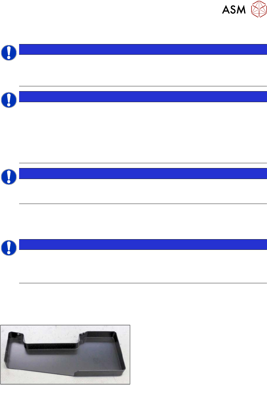
Fig.397: Component sensor protective cap [03092400‑xx]
●
Component sensor protective cap
[03092400‑xx]
●
Calibration tool version SST23 [03034148-xx]
For additional work to the placement head:
●
Head mount [03056231‑xx]
●
Service manual "SIPLACE C&P20P head" [DE:00197489‑xx] [EN:00197490‑xx]
●
Job Card "Preventive Maintenance C&P20P" [DE:00197529‑xx] [EN:00197528‑xx] (other
languages available)
●
If required, for vacuum pump operation: Assembly instructions "Vacuum pump SIPLACE X-
Series S, SX4/DX4" [00196845-xx]
8 Head exchange
8.5 Replacing the SIPLACE C&P20P/M2
314 Service Manual SIPLACE X-Serie S 06/2019
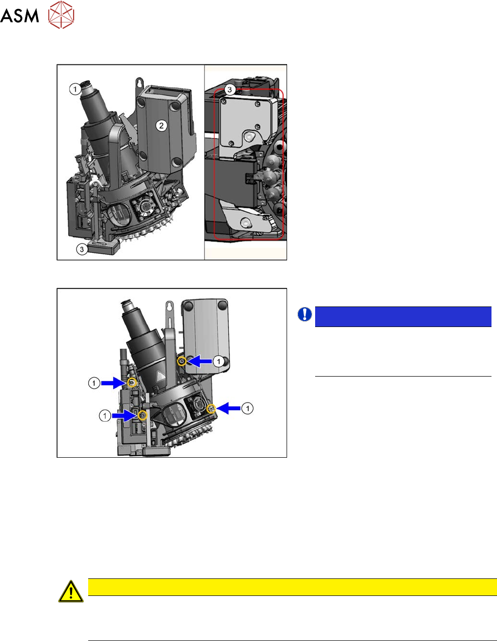
Overview
Fig.398: SIPLACE C&P20P
1. Holding circuit connection
2. Intermediate distributor board (behind
the cover)
3. Component sensor
Fig.399: Fastening screws
1. Four fastening screws (yellow marks)
NOTICE!
The length of the exhaust air hose "Sil-
icon hose Di8 Da12 electrically con-
ductive 1m" [03006727Sxx] on the
SIPLACE C&P20P/M2 is 355mm.
.
Removal
► Switch off the machine, disconnect it from the power supply and secure it to prevent
unauthorized reactivation.
1.2 "Preparatory work..." [}16]
► Switch off the compressed air supply
5.2 "Disabling the compressed air supply" [}134]
CAUTION
Take great care when dismantling the placement head!
The component sensor prisms, underneath the placement head, could be damaged.
► Never place the placement head down on the component sensor.
► Fit the protective cap onto the component sensor for the placement head.