00197042-04_SM_X-Serie-S_Customer_EN.pdf - 第319页
8 Head exchange 8.6 Replacing the SIPLACE CPP/M Service Manual SIPLACE X-Serie S 06/2019 319 8.6.1 Preparing the SIPLACE CPP for the installation height CAUTION Different heights The placement head can be installed at tw…
8 Head exchange
8.6 Replacing the SIPLACE CPP/M
318 Service Manual SIPLACE X-Serie S 06/2019
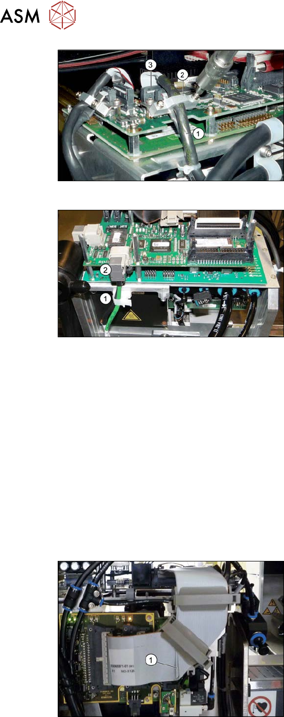
Fig.406: Cables (up to Gxxxx, without GigE)
Up to Gxxxx, without GigE:
► Remove the screws fastening the strain
relief (2) on the component camera cable
(1) and carefully unplug the cable. While
unplugging the cable press the clamps
on both sides of the connector(3). You
may want to mark the positions to make
clear assignment easier later on.
Fig.407: Cables (from Hxxxx, with GigE)
From Hxxxx, with GigE:
► Open the cable holder(1) and unplug the
component camera cable(2).
► Remove all four screws fastening the head with a long Torx screwdriver.
► Carefully lift the head out of the locating pins on the head plate and off the hook.
► Placing the head into the head transport box
Installation
► Follow the removal instructions in reverse order for installation. Also observe the following
instructions:
– If you replace the head without the component camera, you will need to fit the old camera onto
the new head. Read the service manual for your placement head for more information.
– Observe the correct installation height of the head (top or bottom position, see 8.6.1 "Pre-
paring the SIPLACE CPP for the installation height" [}319])!
– Make sure that the assembly position on the head plate is correct.
– Tighten the four fastening screws with a torque of 2.7Nm.
– Make sure that the flat ribbon cable is run correctly to the head adapter (see below).
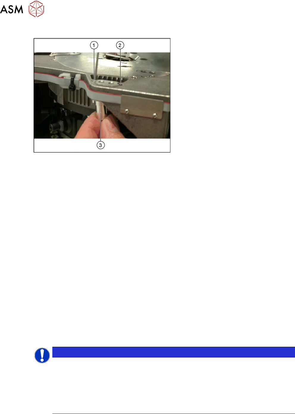
Fig.408: Flat ribbon cable
Correct running of flat ribbon cable to head
adapter
► Make sure that the flat ribbon cable is run
correctly to the head adapter. In particu-
lar, the cables must lie inside one an-
other at the 90 degrees turn(1) and not
on top of one another, otherwise the con-
nections on the head adapter could be
easily confused.
See also
2 8.8 "Installation Positions on the Head Plate" [}323]
8 Head exchange
8.6 Replacing the SIPLACE CPP/M
Service Manual SIPLACE X-Serie S 06/2019 319
8.6.1 Preparing the SIPLACE CPP for the installation height
CAUTION
Different heights
The placement head can be installed at two different heights. CPP_L corresponds to a
component height of sixmm. CPP_H corresponds to a component height of 11.5mm.
If the SIPLACE CPP is used in a placement area with stationary camera, SIPLACE Twin or
SIPLACE WPC, it may only be used in the upper position!
Overview
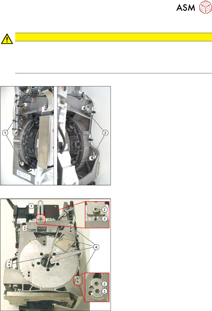
Fig.409: Fastening screws
1. Fastening screws on the left side
2. Fastening screws on the right side
This diagram shows the fastening screws in
the "head at top" position.
Fig.410: SIPLACE CPP – positions
1. Retaining plate
2. "Head at bottom" position
3. "Head at top" position
4. Fixture holes with bushings
8 Head exchange
8.7 Replacing the SIPLACE Twin
320 Service Manual SIPLACE X-Serie S 06/2019
Conversion to another installation height
Fig.411: Conversion
1. Hole for the fastening screw of the
bushing in "head at bottom" position
2. Hole for the fastening screw of the
bushing in "head at top" position
3. Bushing
All four bushings and the retaining plate
must either be fixed in top or bottom posi-
tion.
Proceed as follows when replacing the
bushings:
► Undo the fastening screws of the bush-
ings.
► Insert the bushings in the correct posi-
tion and re-tighten them.
► Perform these steps for all four fasten-
ing bushings and the retaining plate for
the head.
8.7 Replacing the SIPLACE Twin
Parts, equipment and tools
●
Select the relevant placement head:
– Twin Pick&Place module [03033628-xx]
– Twin Pick&Place module THK R2 [03097485-xx]
●
Torque screwdriver 1-5 Nm [03078400-xx]
●
Extension/straight TX20 [03073256-xx]
●
Extension/straight [03043440-xx]
●
Bit holder for Torque Vario-S screwdriver [03078706-xx]
●
Calibration tool version 3 [03010565-xx]
●
For additional work on the placement head:
Head assembly stand [03056231‑xx]
Service manual "Twin/VHF" [DE: 00197468-xx]. [EN: 00197469-xx]
Job Card "Preventive Maintenance Twin" [DE:00197604‑xx] [EN:00197603‑xx] (other lan-
guages available)
Overview
The Twin consists of two identical Twin segments, which are fitted at an angle of 180°.
NOTICE
Module 1 and 2
The removal procedure is described here for module1 (left). Removal for module 2 (right)
is the same.
► In the case of older Twins, module 1 might need to be removed before you can
remove module 2. When fitting them again, you would then need to fit module 2 first,
before module 1.
► In the case of newer Twin heads, the modules can be removed and fitted individually.