00197042-04_SM_X-Serie-S_Customer_EN.pdf - 第32页
2 Basic Machine 2.4 Setting the Covers 32 Service Manual SIPLACE X-Serie S 06/2019 2.4.3 Setting the Cover Switch Centering Device Fig.19: Cover switch (example of SIPLACE SX2 shown) ► Close the cover a little more unti…
2 Basic Machine
2.4 Setting the Covers
Service Manual SIPLACE X-Serie S 06/2019 31
2.4 Setting the Covers
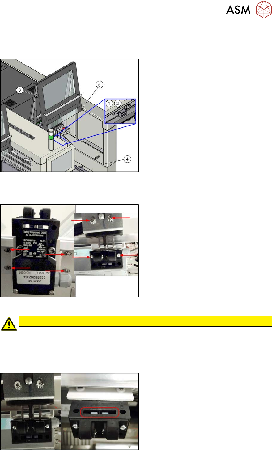
2.4.1 Overview
Fig.16: Overview of Settings
1. Setting the cover switch
See 2.4.2 "Setting the Cover
Switch" [}31]
2. Setting the cover switch centering
See 2.4.3 "Setting the Cover Switch
Centering Device" [}32]
3. Setting the actuator
See 2.4.4 "Setting the Actuator" [}32]
4. Setting the bottom stop
See 2.4.5 "Setting the Bottom
Stop" [}33]
5. Setting the rollers
See 2.4.6 "Setting the Cover
Rollers" [}34]
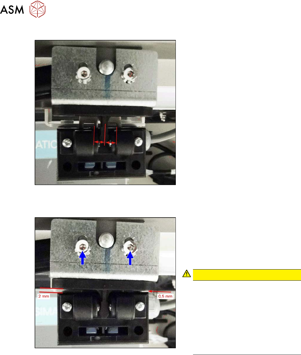
2.4.2 Setting the Cover Switch
Fig.17: Cover switch (example of SIPLACE SX2 shown)
Cover switch [03055262-xx]
► Loosen the screws fastening the cover
switch, the centering device and the ac-
tuator, so that the assemblies can be
easily moved.
CAUTION
Screws on actuator
With enforcement of the Machinery Directive DIN EN 1088 (2009), the following has been
executed to avoid misuse (e.g. putting the safety features out of action): the actuator and
machine protective switch screws have been replaced by Torx screws with pins. The relev-
ant set of tools may only be used for performing repair work.
Fig.18: Cover switch (example of SIPLACE SX2 shown)
► Close the cover far enough for the actu-
ator to be just over the switch. Align
them so that the metal bracket is parallel
to the opening in the switch. The metal
bracket may not scrape against the
cover switch.
► Tighten the cover switch screws in this
position.
2 Basic Machine
2.4 Setting the Covers
32 Service Manual SIPLACE X-Serie S 06/2019
2.4.3 Setting the Cover Switch Centering Device
Fig.19: Cover switch (example of SIPLACE SX2 shown)
► Close the cover a little more until the
plastic centering device for the actuator
is against the cover switch centering
device. These two must be centered to-
wards one another.
► Tighten the screws for the cover switch
centering device.
2.4.4 Setting the Actuator
Fig.20: Setting (example of SIPLACE SX2 shown)
Actuating bracket B1-2053 for AZ15/16
[00321649‑xx]
► Close the cover completely.
► Set the actuator so that it stands ap-
prox. 2 mm above the machine center
and tighten the screws.
CAUTION!
The cover switch is not suitable as a
stop.
The cover switch is not a stop or a
support for the cover. Use the bottom
stops of the rollers for this (see next
section).
Neither the cover nor the actuator may
be supported on the cover switch.
There must be a visible gap between
the actuator and the cover switch.
.
2 Basic Machine
2.4 Setting the Covers
Service Manual SIPLACE X-Serie S 06/2019 33
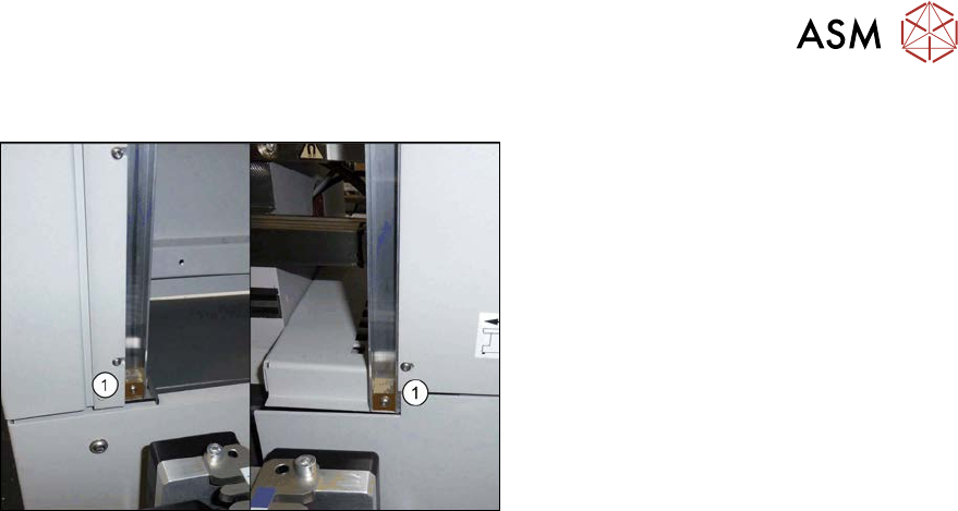
2.4.5 Setting the Bottom Stop
Fig.21: Bottom stop
1. 2x buffer cover guidance [03075364‑xx]
1x DIN EN ISO7380-M3 x 25-A2-70
[03045198‑xx]
1x DIN985 - M3 - A2-70 [00328897‑xx]
► Check the settings by opening and carefully closing the cover several times:
– The metal bracket is parallel to the opening and does not scrape against the switch.
– The plastic centering feature is positioned centrally to the centering device and does not
scrape against the switch.
– When the cover is opened, there is no discernable resistance of the cover rollers in the
guidance rails.
– Shortly before the bottom cover position, there is no resistance audible apart from the cen-
tering engaging and the engaging of the metal bracket in the cover switch.
– The cover can be closed completely, so that the cover closes smoothly at the top with the
side covers.